Haul Roads
Note: Haul Road Analysis is an add-on that requires additional licensing, which may be obtained via your Maptek Account portal. Please see Licensing Applications in Workbench help for details.
The Haul Roads tools on the Query tab analyse and report on haul roads to assist with design and construction, and maintenance.

|
|
Analyse dimensions of haul road features. |
|
|
Generate a report from haul road analysis results. |
Haul Road Analysis
Note: Well designed and maintained haul roads are a key to minimising costs and improving productivity. The haul road analysis tool is licensed through Maptek account.
The Haul Road Analysis tool assists in identifying areas of haul roads for possible issues, and allowing changes to the road design to be made.
The haul road analysis tool addresses the following parameters:
-
Haul road width
-
Haul road grade
-
crossfall or camber
-
Safety berm or bund height
-
Safety berm or bund widths
Analyse haul roads, as follows:
-
Create a 3D CAD surface
 of the mine site.
Note: The input data can be sourced from any type of sensor or package.
-
Import the surface.
-
View the surface in a new view window.
-
Using the
 Line tool create an approximate line along the centre of the road.
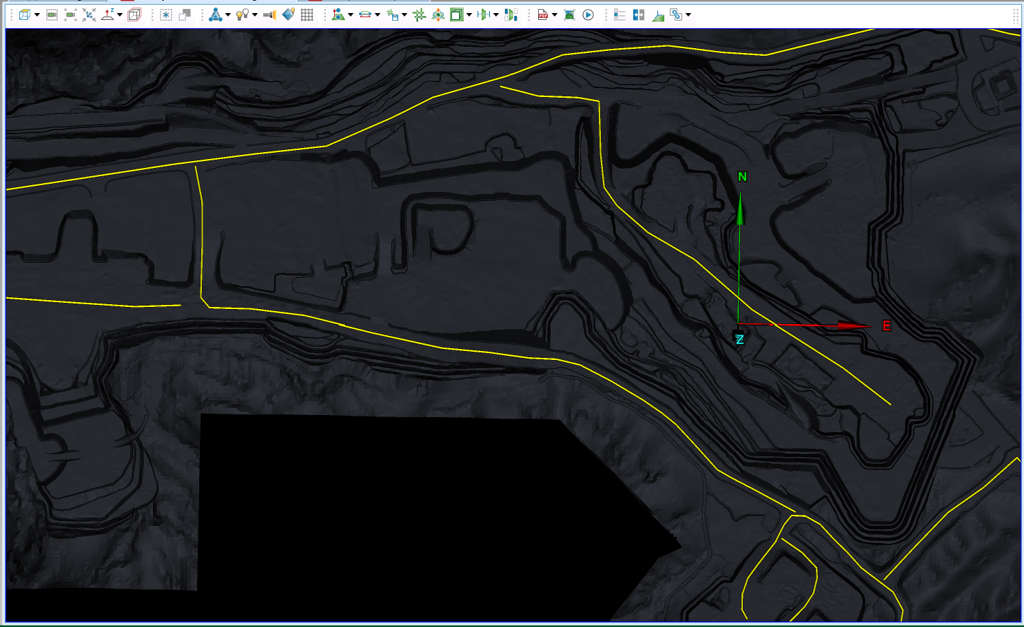
-
On the Query tab, in the Haul Roads group, click
 Haul Road Analysis.
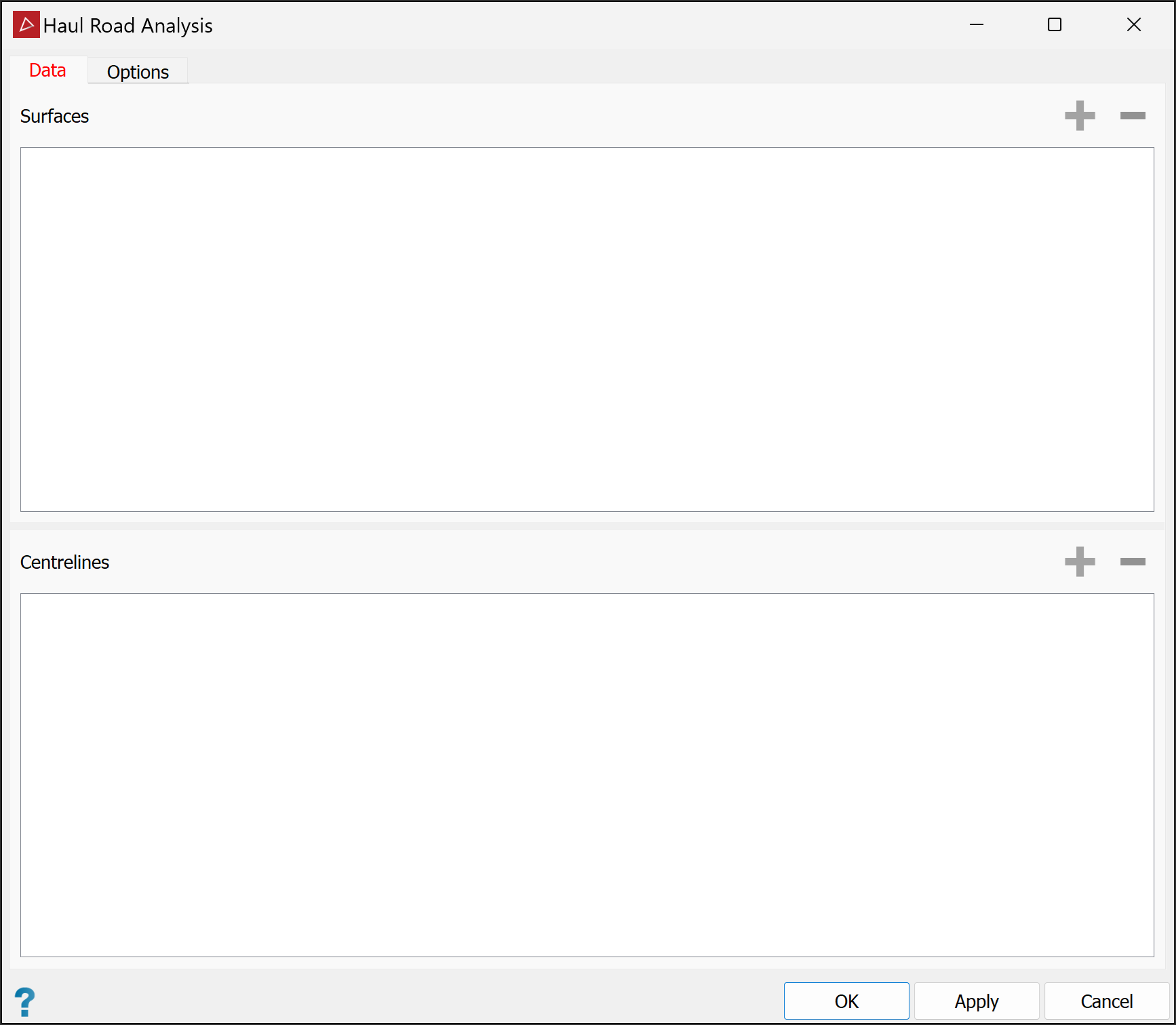
The Haul Road Analysis panel will open.
-
To populate the Data panel, select the surfaces or triangulations of the mine site and the centre lines of the road In the project explorer.
-
Click both the
 buttons to populate the fields with the data. PointStudio will automatically add the objects to the appropriate fields.
 -
Select the Options tab.
-
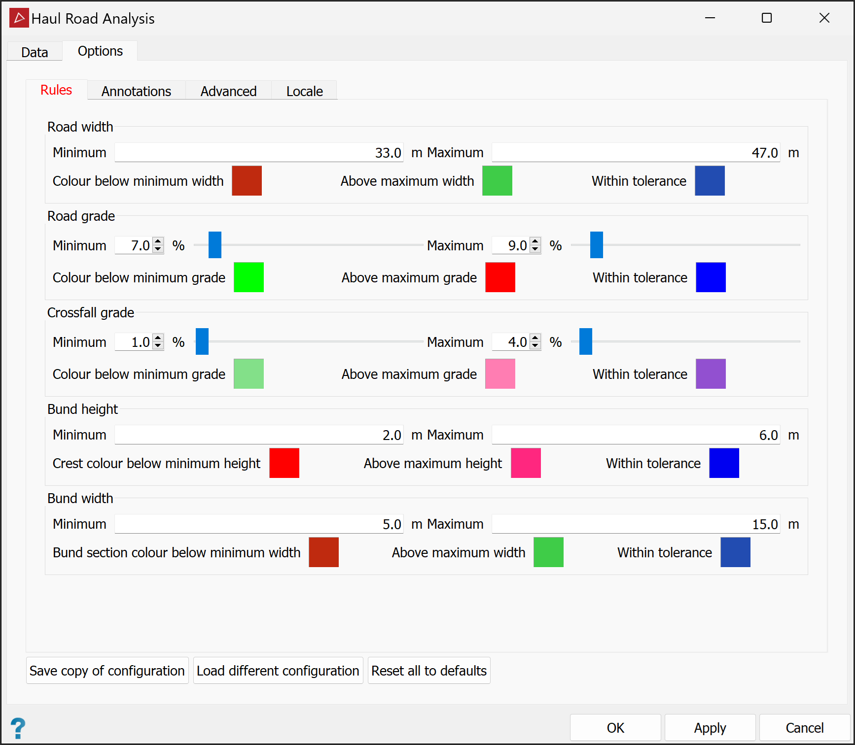
In the Rules tab you can set Minimum and Maximum values for the following parameters, and define colours to depict the areas of the road that are above, within and below tolerances:
-
Road width
-
Road grade (%)
-
Crossfall grade (%)
Note: If the tool detects an upward grade from the centre line, it too will be flagged as above maximum.
-
Bund height
-
Bund width
-
-
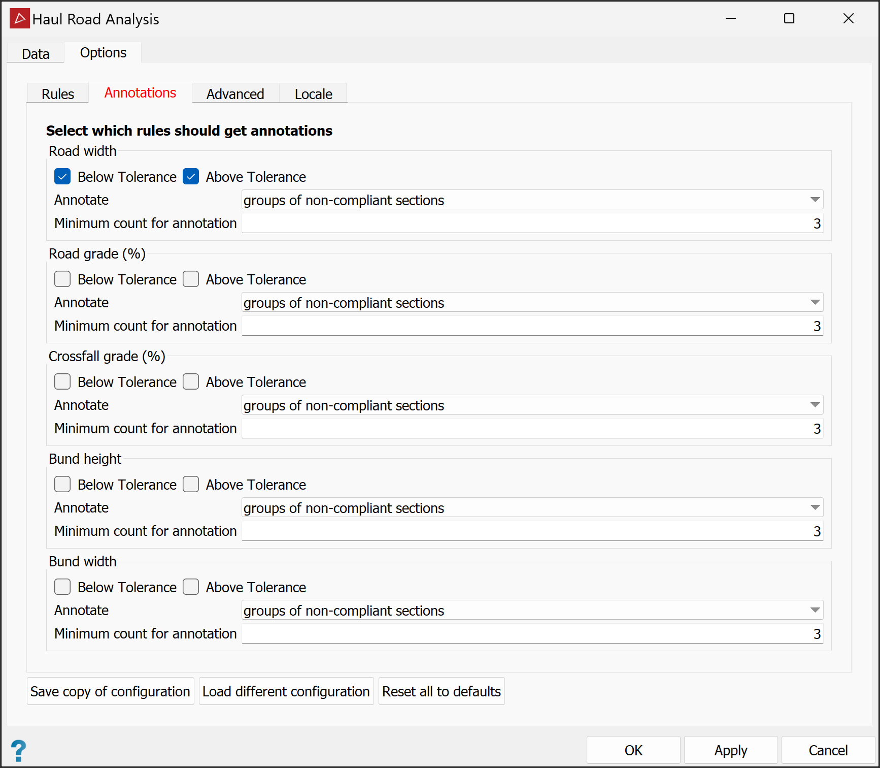
Select the Annotations tab to choose the required annotations. For each measurement, you can annotate in either of the following ways by selecting from the Annotate drop-down lists:
-
groups of non-compliant sections: Enter the required Minimum count for annotation, being the minimum number of contiguous cross-sections meeting the criteria for an annotation to be created.
-
every non-compliant section individually: The annotation is applied to all non-compliant sections, regardless of location.
-
-
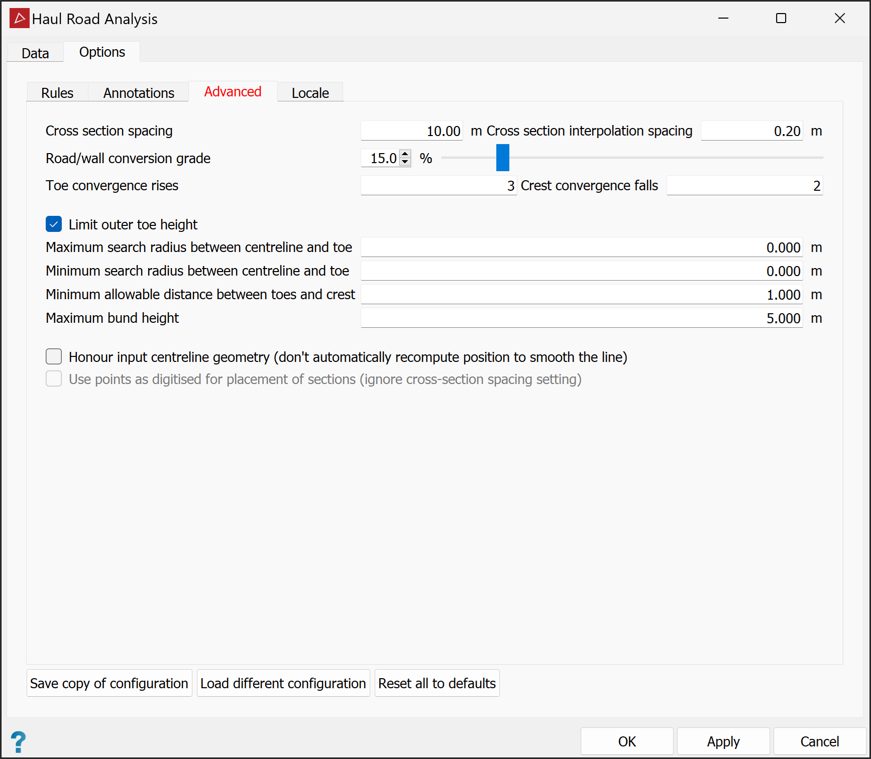
Select the Advanced tab where you can set the parameters below.
-
Cross Section Spacing: Increase or decrease the number of sections by adjusting the cross section spacing.
-
Cross Section interpolation spacing: Intervals at which each section is sampled, looking for grade or change in direction.
-
Road or wall conversion grade: The angle needed in the interpolation spacing to detect a change from haul road to a wall or bund.
-
Toe convergence rises: The number of subsequent upward points needed to create a toe.
-
Crest convergence falls: The number of subsequent downward points needed to create a crest.
-
Limit outer toe height:
-
If selected, the outer toe will be calculated in line with the inner toe height. This is best for pits with spiralling roads.
-
If cleared, all of the outer toe will be drawn to the next closest toe.
-
-
Maximum search radius between centreline and toe: The farthest from the centreline that the tool will search for a toe.
-
Minimum search radius between centreline and toe: The nearest to the centreline that the tool will begin to search for a toe.
-
Minimum allowable distance between toes and crest: The acceptable distance between toes and crest.
-
Maximum bund height: The height threshold for distinguishing between bunds at the sides of roads and at the tops of walls.
-
Honour input centreline geometry:
-
If selected, the tool will use the centreline created by the operator.
-
If cleared, the tool will create a smooth road line by smoothing out any sharp corners in the centreline.
-
-
Use points as digitised for placement of sections:
-
If selected, the tool will create cross sections at the digitised locations.
-
If cleared, the tool will create cross sections equally spaced as specified above.
-
-
-
In the Locale tab, select and rename output destination containers as required.
Note: The

scrapbookcontainer is the default parent container for the destination containers. You can change this in the Destination field.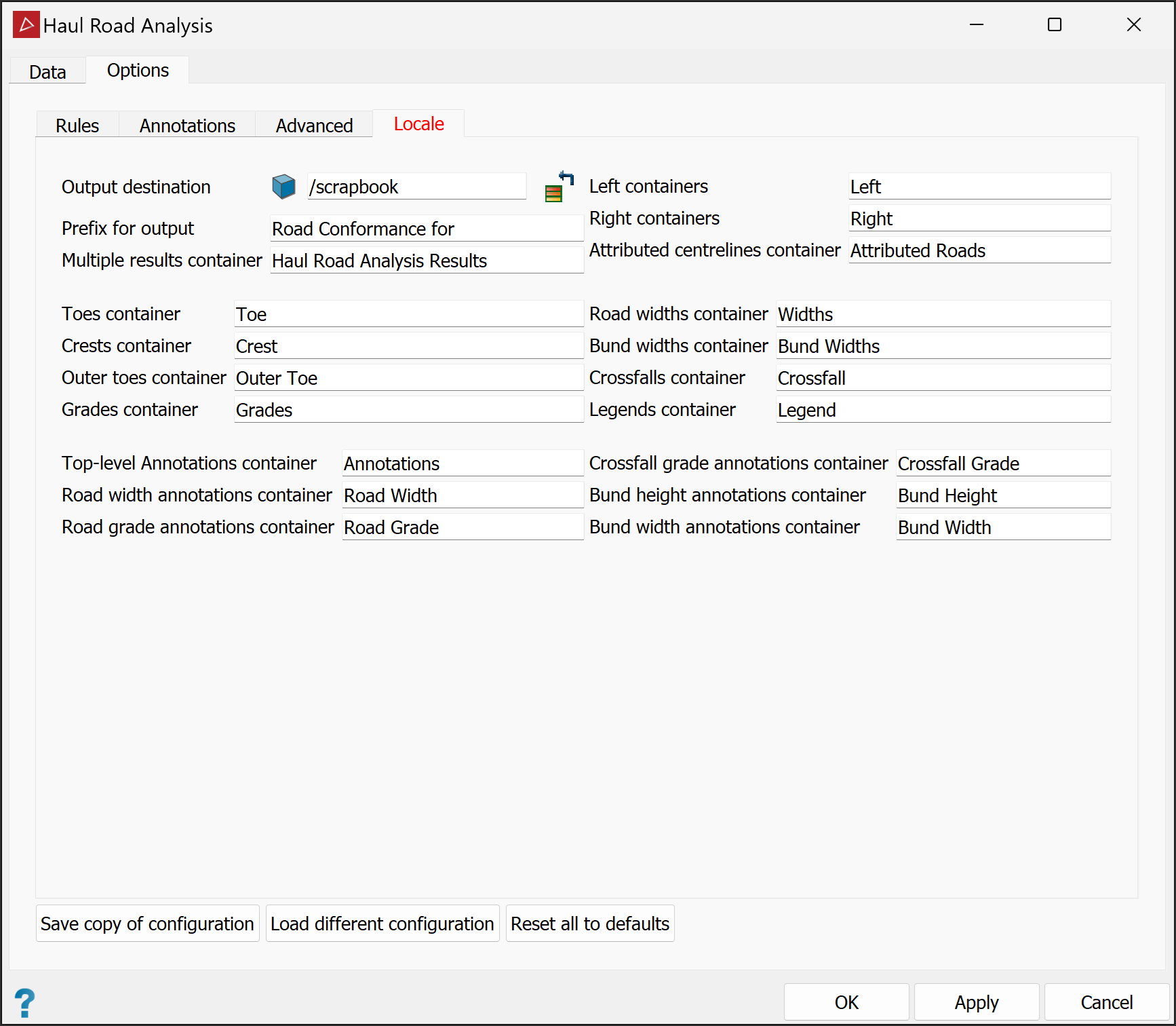
-
Click the buttons at the bottom of the panel per your requirements:
-
Save copy of configuration for later recall for another job.
-
Load different configuration to recall previously saved settings.
-
Reset all to defaults to undo all changes.
-
-
Click OK or Apply.
-
To inspect the results, drag them from the destination containers into a view window.
|
|
|
An example of a haul road analysis with all the results grouped and exported into their relevant containers. The legends are compiled from the option rules. Annotations are for road widths only. |
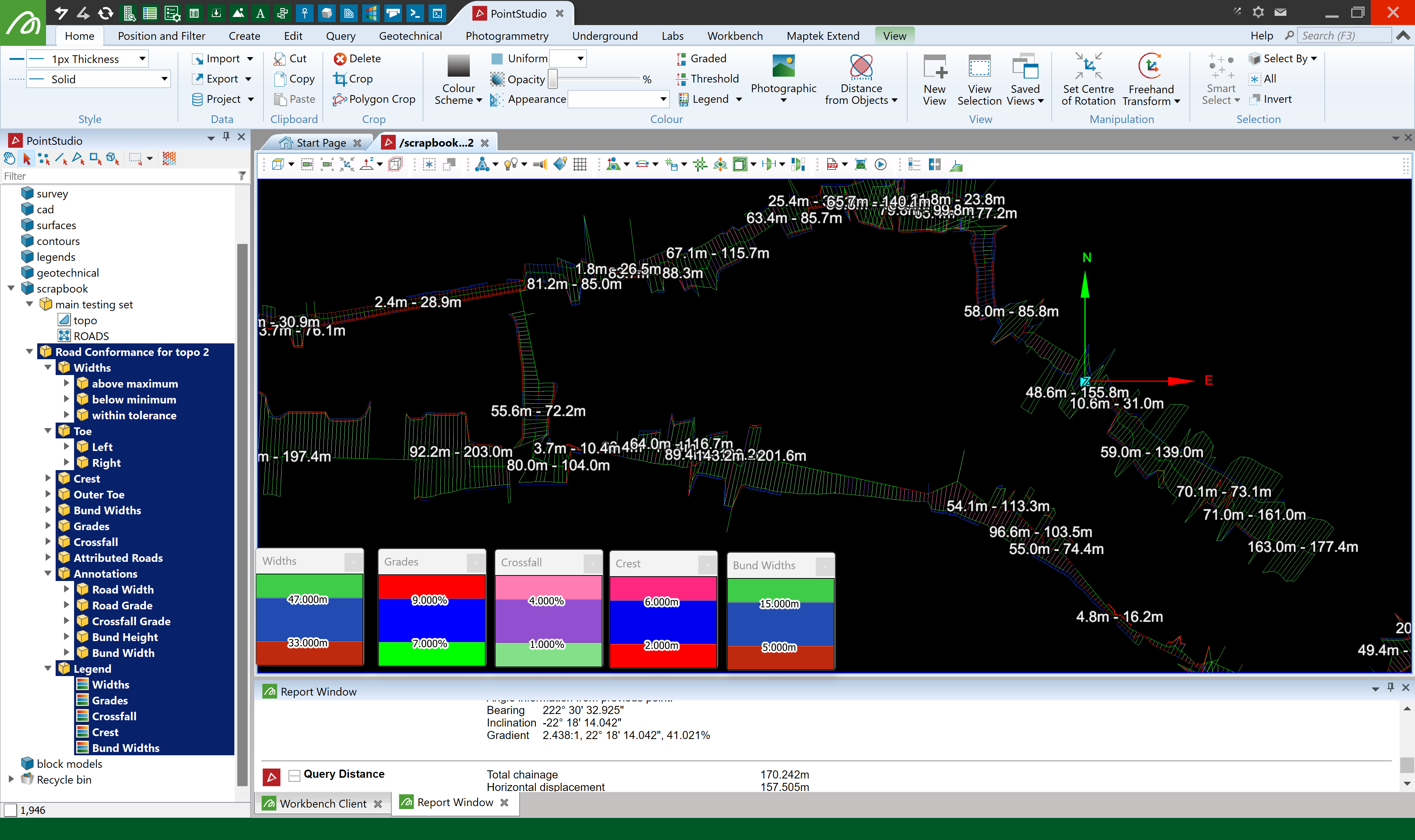
Tip: The Widths lines and the Crossfall lines will overlap each other and the colours will mesh. To visualise each line separately use the visibility editor to hide one and view the other.
Haul Road Report
The Haul Road Report tool enables you to generate a report from the haul road analysis results, including images and graphs, that can then be exported to PDF or a CSV format.
To generate a haul road report, proceed as follows:
-
On the Query tab, in the Haul Roads group, click
 Haul Road Report.
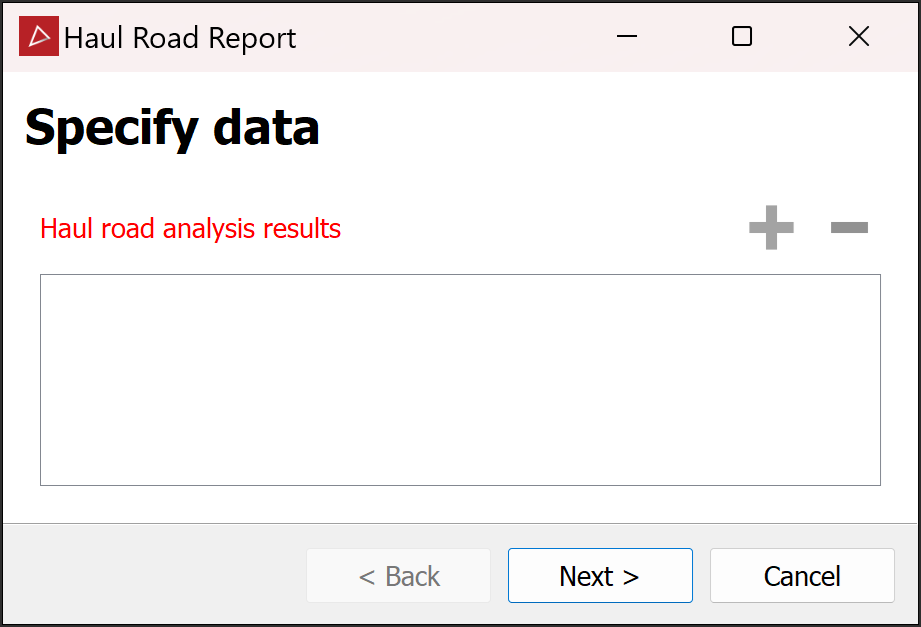
-
Add the haul road analysis results to the panel. Either select the results in the project explorer and click the
 button or drag them into the panel.
 -
Click Next >.
Tip: Resize and reposition the panel for better visibility of both the view window and options. You can also adjust column widths.
-
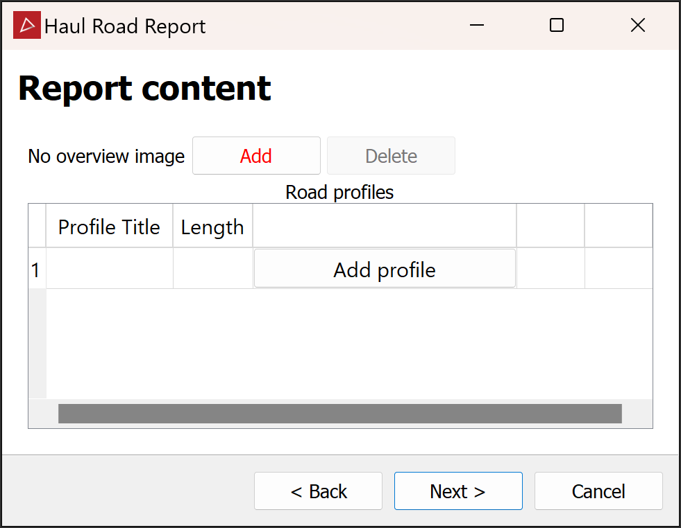
(Optional) Arrange the active view window as appropriate, then click Add to create an overview image for the report.
TipWhen you have created an overview image:
-
The Add button changes to Edit.... Click to open the image in your default image editor and make any changes you want.
-
The Delete button is enabled. Click if you need to delete the overview image.
-
-
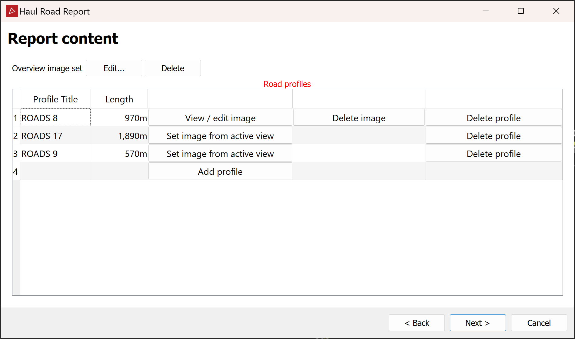
Add sections of interest to the Road profiles table. Click Add profile in the first available row, then pick the start and end points in the view window. Manipulate the view as necessary. The profile will be added to the table. For each road profile in the table, the following options become available:
-
Set image from active view. Click to generate an image of the active view window.
Note: Images capture the active view as it appears. All road profiles in view are included in the image regardless of which button you click.
-
View / edit image. This option appears for any profile that has an associated image. Click to view and edit the image in your default image editor.
-
Delete profile. Click to delete a profile that is not required.
-
Delete image. Click to delete an image that is not required.
Tip: To rename a profile, click on its current name under Profile Title, then type the new name and press Tab.
-
-
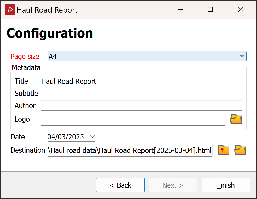
Click Next >.
-
Select the required Page size from the drop-down.
Note: Page orientation is not selectable; pages are always in landscape.
-
(Optional) Enter the required metadata, including your company logo.
-
(Optional) Change the date to reflect the date the data was collected.
-
(Optional) Browse to the preferred output destination.
-
Click Finish to create the report.
