Rose Diagram
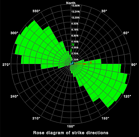
The Rose Diagram tool (Geotechnical tab > Analyse group) plots the frequency of data against the direction of the data. Rose diagrams help to identify directional trends in the data.
Before creating a rose diagram, you must prepare stereonet data from discontinuities. See Create Stereonet > Create Stereonet.
Once you have the data prepared, follow these steps to create the rose diagram:
-
Highlight all the created discontinuities in the project explorer.
-
On the Geotechnical tab, in the Analyse group, click
 Rose Diagram.
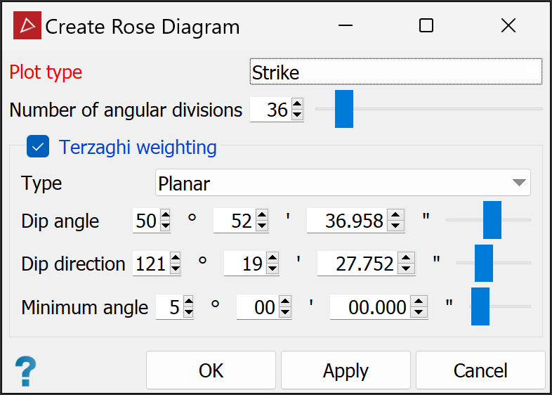
- Select
the Plot type from the drop-down
list:
Strike direction plots the strike direction of the planes.
Dip direction plots the dip direction of the planes.
Trend direction plots the trend direction of the planes.
-
Specify the Number of angular divisions required in the diagram (range 2-360).
-
(Optional) Select Terzaghi weighting if required. Terzaghi weighting uses the measurement orientation to counteract sampling bias. Configure weighting parameters as follows:
-
From the Type drop-down, select the required weighting method:
-
Planar gives bias to discontinuities less likely to intersect the specified plane.
-
Linear gives bias to discontinuities less likely to intersect the specified line.
-
-
Set the Dip angle and Dip direction (for planar type) or Plunge and Trend (for linear type).
Tip-
For planar type, create a discontinuity object of the whole slope face with the dip and strike
 Query tool, then drag the discontinuity object into the dip fields of the Stereonet Contours panel.
 -
For linear type, create a discontinuity object of the linear feature, then drag the object into the plunge and trend fields of the Stereonet Contours panel.
-
-
Set the Minimum angle as the lowest angle between the measurement orientation and the discontinuity that may be used for weighting.
-
-
Click OK or Apply.
The
rose diagram components are saved in a custom container ![]() inside the
inside the ![]()
geotechnical container.
|
|
|
The direction of the data is displayed around the circumference of the diagram and the frequency of the data is displayed on the radius. |