Lines and Polygons
The Line and Polygon drop-downs (Create tab > Draw group) provide tools for drawing lines and shapes in the project, by different methods.
A line consists of one or more straight line segments between selected points.
Polygons are closed lines or loops used to define boundaries, consisting of three or more straight line segments between selected points. Use polygons to define areas of interest for modelling, filtering, and cropping data. You can draw irregular polygons, rectangles, or circles.
PointStudio saves the resultant lines and polygons in the ![]()
cad container.
Line and Polygon
Draw lines or polygons in 3D space with either the Line tool (F9) or the Polygon tool (F10). Expand below for instructions.
Tip: Create lines while in top view ![]() or action plane front view
or action plane front view ![]() , or use snap
modes to ensure the lines are placed in the intended locations.
, or use snap
modes to ensure the lines are placed in the intended locations.
-
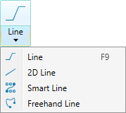
On the Create tab, in the Draw group, select
 Line from the Line drop-down list.
A panel will open displaying the input fields for the First point.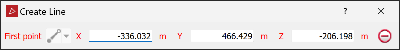
-
Pick the First point in the view window, or enter coordinates manually in the X, Y, and Z input fields. Click the
 button to clear the input fields.
The Next point drop-down will be enabled, from which you can select one of the following the coordinate entry modes:

Point
Enter or pick the next point's coordinates.

Length, bearing and inclination
Enter the length, compass direction, and inclination angle of the next line segment.

Relative offset
Enter the next point's distance from the last point in the X, Y, and Z directions.
-
Enter or pick as many points as required to build a line using the preferred coordinate entry mode, or by clicking on the action plane.
-
Right-click to complete the line.
-
Repeat the above steps to create another line.
-
Press Esc or click the
 button to exit the tool,
or continue creating new lines.
button to exit the tool,
or continue creating new lines.
-
On the Create tab, in the Draw group, select
 Polygon from the Polygon drop-down list.
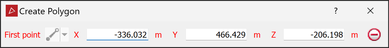
The tool panel will open displaying the input fields for the First point.
-
Pick the First point in the view window, or enter values manually in the X, Y, and Z input fields and press Enter. Click the
button to clear the input fields.The Next point drop-down will be enabled, from which you can select one of the following coordinate entry modes:
Point
Enter or pick the next point's coordinates.
Length, bearing and inclination
Enter the length, compass direction, and inclination angle of the next line segment.
Relative offset
Enter the next point's distance from the last point in the X, Y, and Z directions.
-
Enter or pick as many points as required to build a polygon using the preferred coordinate entry mode, or by clicking on the action plane.
The point coordinates, length and angle, or plane relative offset will be displayed as the polygon is being created.
-
Right-click to complete the polygon.
-
Repeat the above steps to create another polygon.
-
Press Esc or click the
button to exit the tool,
or continue creating polygons.
Tip: Create polygons while in top view ![]() , or use snap modes to ensure the polygon is created in the intended location.
, or use snap modes to ensure the polygon is created in the intended location.
|
|
|
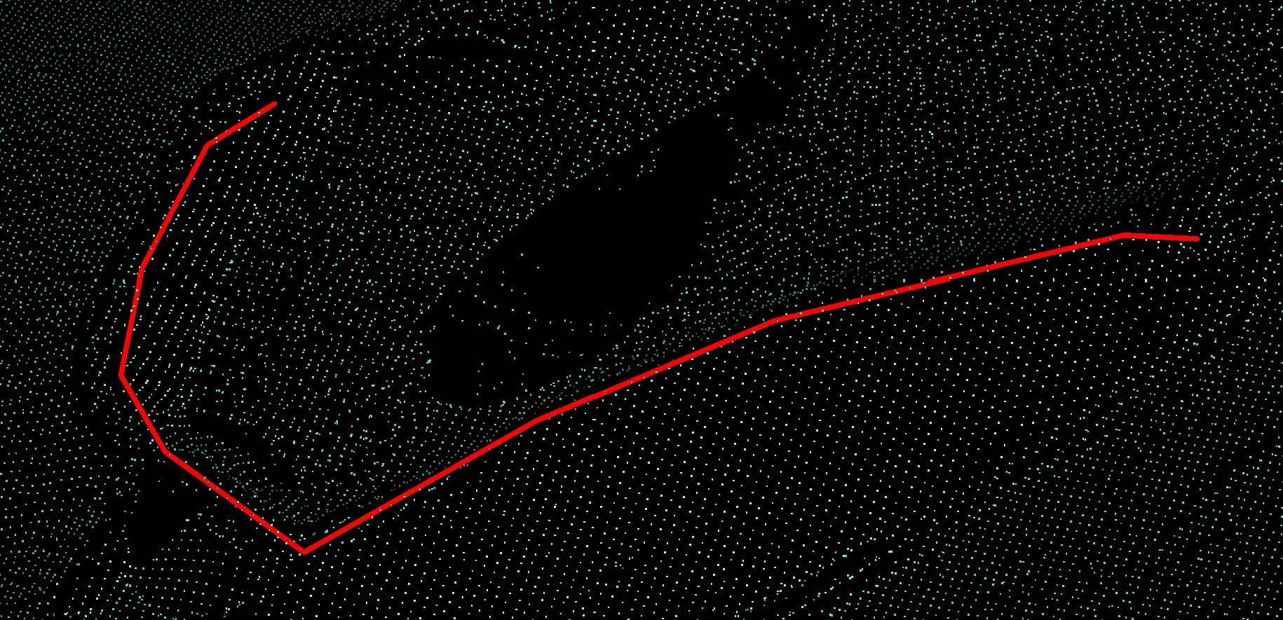
Example of a polygon being created using snap to point mode (left) and completed polygon (right). |
2D Line and 2D Polygon
The 2D Line and 2D Polygon tools enable you to draw lines and shapes on the action plane. The action plane assists in determining line placement in 3D space. Expand below for instructions.
-
Set up the action plane where you want to draw a line.
-
On the Create tab, in the Draw group, select
 2D Line from the Line drop-down list.
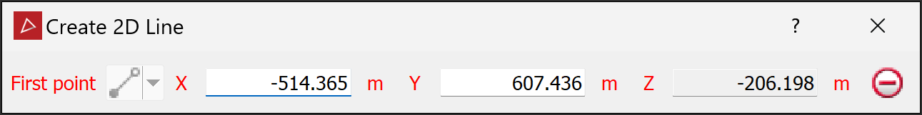
The panel will open, allowing manual input of coordinates for points. You can also select points in the view window.
-
Click in the view window to select the first point, or enter values manually in the X and Y input fields, then press Enter. Click the
button to clear the input fields.Note-
If an axis is normal to the action plane, that axis input field is disabled.
-
As soon as you start to draw a 2D line, the action plane is locked and cannot be moved until the 2D Line tool is closed.
The Next point drop-down will be enabled, from which you can select one of the following coordinate entry modes:

Point
Enter or pick the next point's coordinates.

Length and angle
Enter the length and compass direction of the next line segment.
Plane relative offset
Enter the next point's distance from the last point in the X and Y directions.
-
-
Enter as many points as required to build a line using the preferred coordinate entry mode, or by clicking on the action plane.
The point coordinates, length and angle, or plane relative offset will be displayed as the line is being created.
-
Right-click to complete the line.
-
Repeat the above steps to create another line.
-
Press Esc or click the
button to exit the tool,
or continue creating new lines.
Note: After you finish the line and exit the tool, the line is detached from the action plane. You can move it as required anywhere in 3D space.
|
|
|
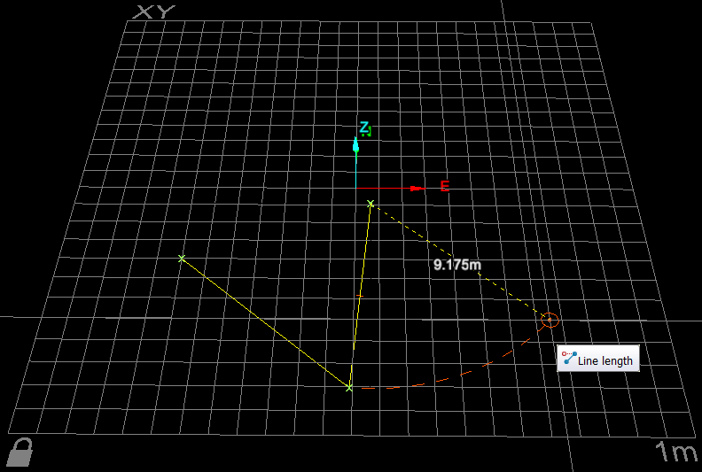
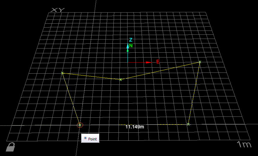
2D line creation. The next line segment's length is displayed according to the mouse's position. |
-
Set up the action plane where you want to place a polygon.
-
On the Create tab, in the Draw group, select
 Polygon from the Polygon drop-down list.
The panel will open, allowing manual input of coordinates for points. You can also pick points on the action plane.
-
Click in the view window to select the first point or enter values manually in whichever X, Y, and Z input fields are enabled and press Enter. Click the
button to clear the input fields.Note: If an axis is normal to the action plane, that axis input field is disabled.
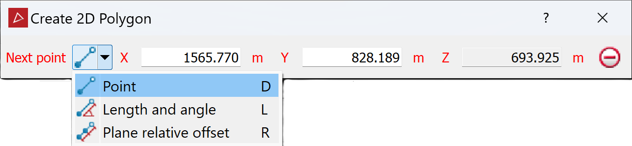
The Next point drop-down will be enabled, from which you can select one of the following coordinate entry modes:
Point
Enter or pick the next point's coordinates.
Length and angle
Enter the length and compass direction of the next line segment.
Plane relative offset
Enter the next point's distance from the last point in the X and Y directions.
-
Enter as many points as required to build a polygon using the preferred coordinate entry mode, or by clicking on the action plane.
The point coordinates, length and angle, or plane relative offset will be displayed as the polygon is being created.
-
Right-click to finish drawing the polygon.
If the polygon is incomplete, the tool will automatically place a line from the last point to the first point, closing the shape.
-
Press Esc or click the
button to exit the tool,
or continue creating new polygons.
Note: After you finish drawing the polygon and exit the tool, the polygon is detached from the action plane. You can move it as required anywhere in 3D space.
|
|
|
2D polygon creation. The next line segment's length is displayed according to the mouse's position. |
Smart Line and Polygon
The Smart Line (F8) and Smart Polygon tools enable you to create lines and shapes that track along edges of data.
The smart line and polygon tools to behave differently with different data types. For example:
-
When tracking along triangulations, the line tracks along physical edges in the surface. This is useful when extracting toes and crests.
-
For coloured scan data, the line tracks coloured edges and extracts geological boundaries.
Tip: Colour the scan non-uniformly before creating smart lines to improve edge selection.
Note: On scans with photographic data ![]() ,
you can use the photographic data to create smart lines with
greater detail. See Create an image-tracking
smart line or polygon below for instructions.
,
you can use the photographic data to create smart lines with
greater detail. See Create an image-tracking
smart line or polygon below for instructions.
-
On the Create tab, in the Draw group, select
 Smart Line or
  Smart Polygonfrom the respective drop-down list.
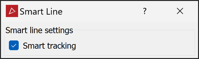
-
Pick the first point in the view window. Build the line or polygon by picking the next points. Pick points close together to ensure that tracking covers all of the points.
Note: You can also enter point coordinates in the status bar. Click
 (Accept content) to accept each point.
 Tip
Tip-
The smart line or polygon tool displays a preview of the next segment before you click to create it. Simply hover the cursor over a point to see where the segment would be placed.
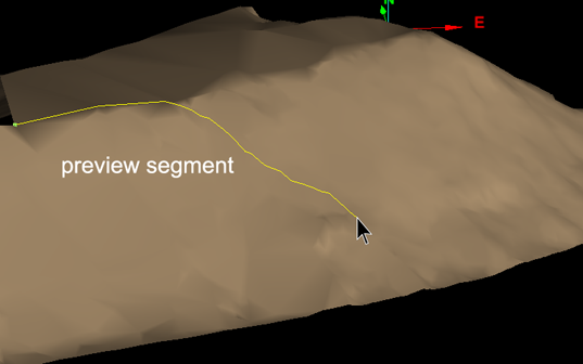
Preview of smart line segment while dragging mouse.
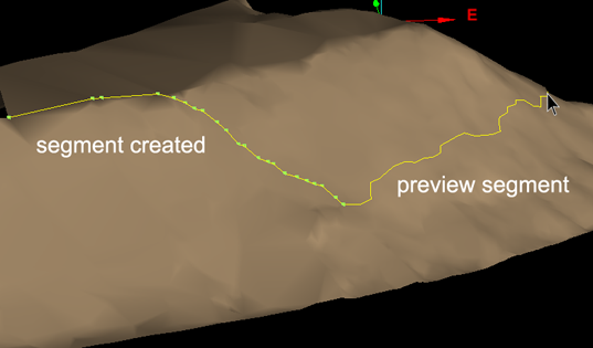
Smart line segment created and new preview segment visible.
-
If the placement of the last segment is unsatisfactory, press Ctrl+Z or click the
 button to undo, then try another point.
 -
If the smart segment cannot be placed satisfactorily, clear the Smart tracking option to create a straight segment between the last and next points. Select Smart tracking again to resume smart tracking.
-
-
When you have selected all the points to construct the smart line or polygon, click
 (Complete). A line will terminate at the last selected point and polygon will close with a straight line to the first point.Note
A smart line may include self-intersections resulting from the path chosen by the software. When this happens, the following message is displayed.
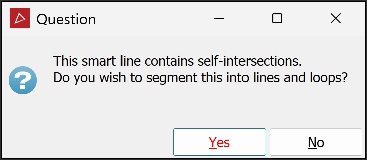
Click Yes to break the line into separate lines and loops, or No to create it as a single edge network.
-
Repeat to create another smart line or polygon.
-
Right-click, press Esc or click
 (Cancel) in the status bar to exit the tool.
Note: This method of creating a smart line or polygon is memory-intensive and will take longer to complete.
-
View and select the scans.
-
On the Position and Filter tab, in the Scan group, click
 Connect.
 -
Right-click on the scan, then hover over
 View and select Photographic Surface.
 -
On the Create tab, in the Draw group, select
Smart Line or Smart Polygon from the respective drop-down list, and proceed as
for a primitive-tracking line or polygon.
|
|
|
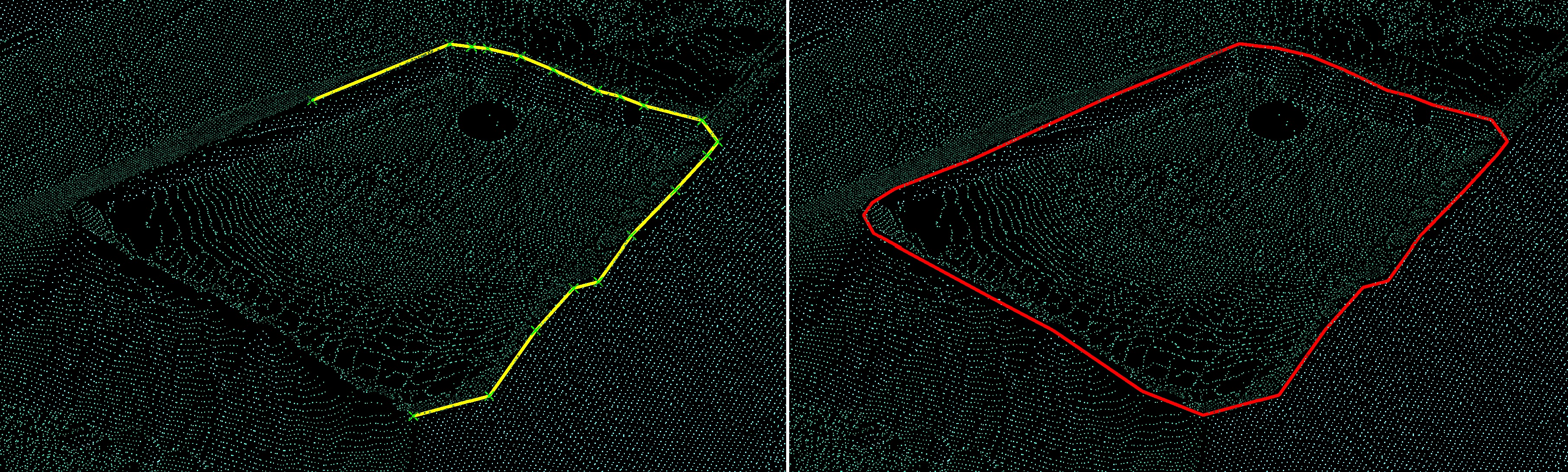
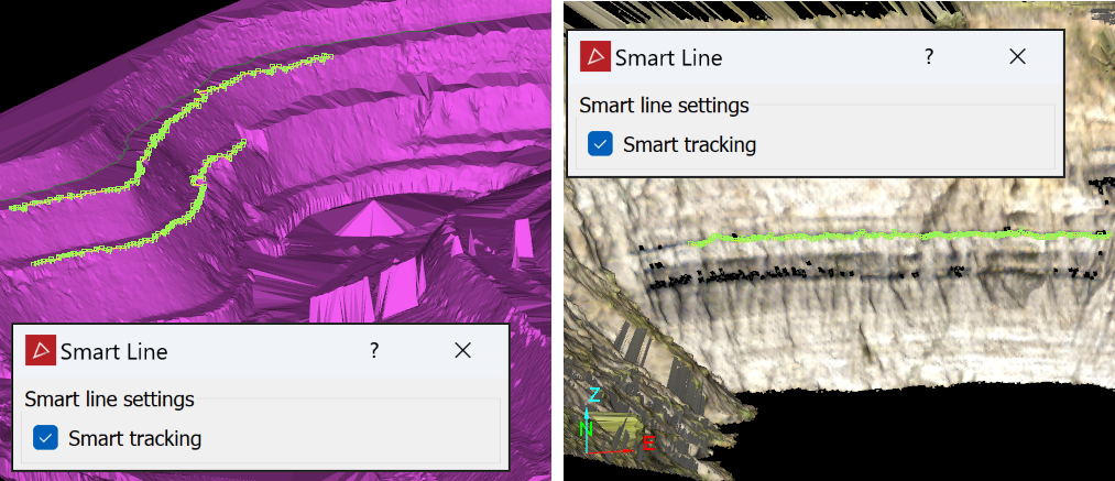
Primitive-tracking smart lines (left) and an image-tracking smart line (right) |
|
|
|
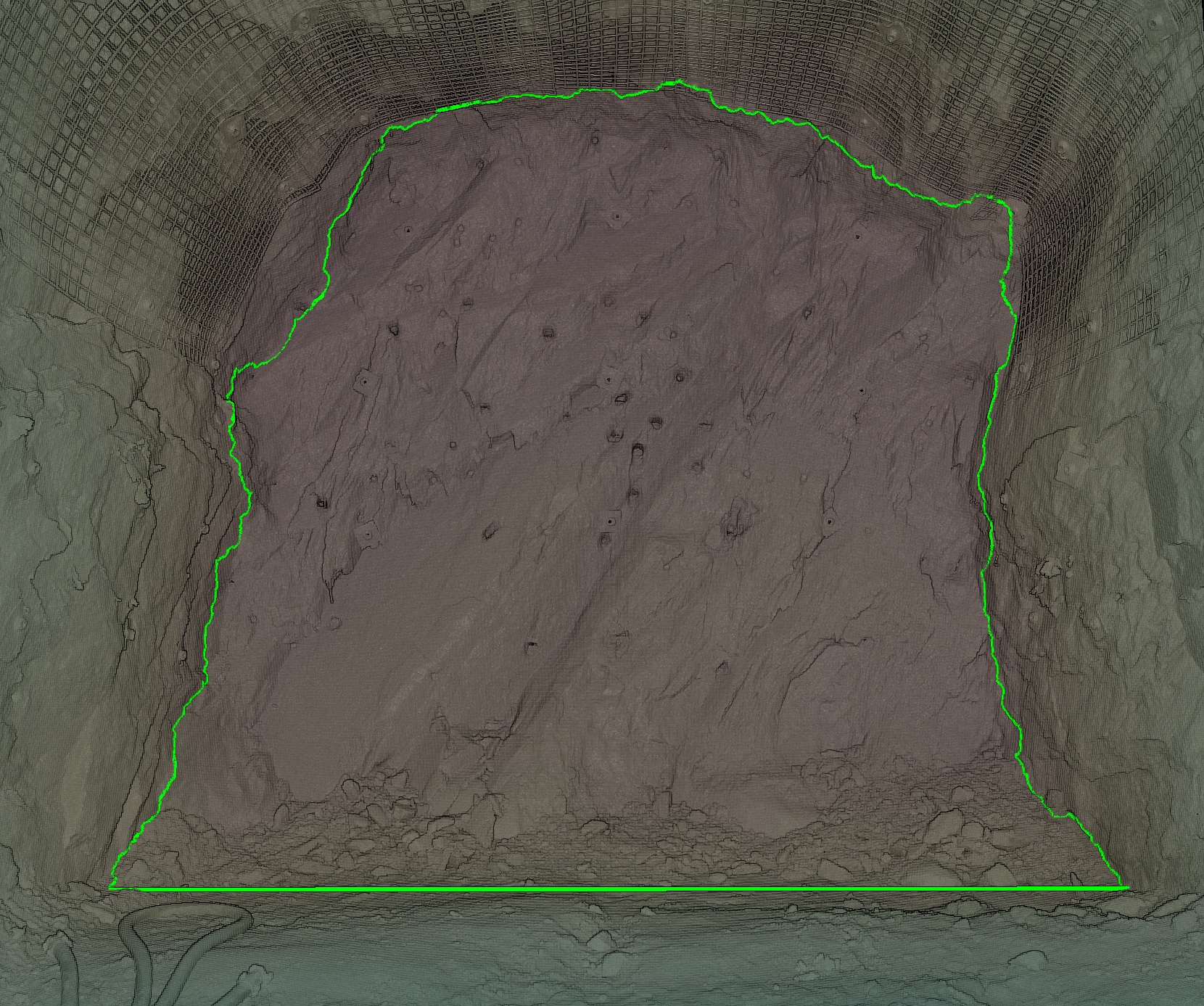
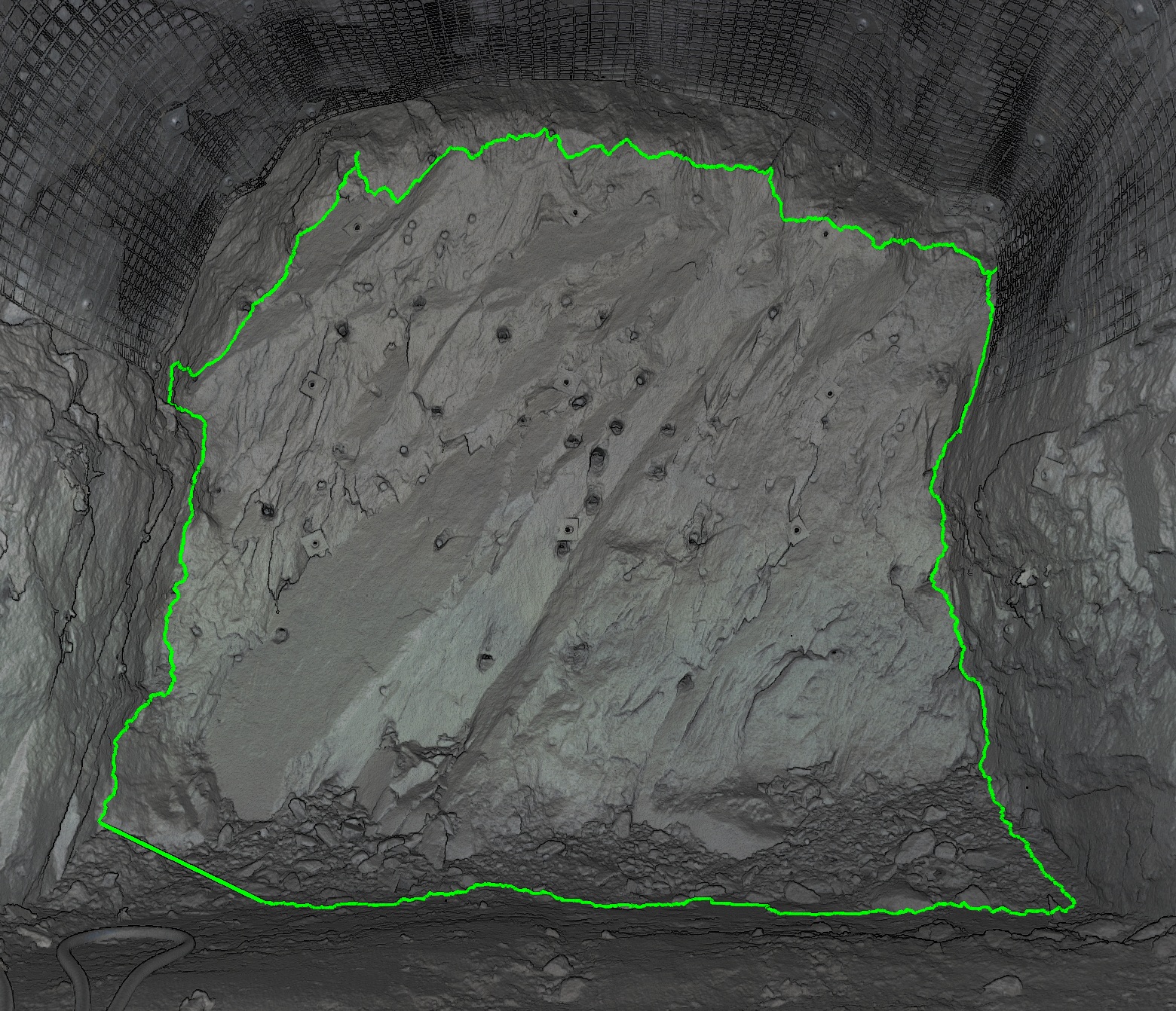
Primitive-tracking smart polygon (left) and an image-tracking smart polygon (right) |
|
Freehand Line and Polygon
The Freehand Line and Freehand Polygon tools enable you to draw lines and shapes anywhere in 3D space along the path of the moving mouse.
Note: Where the mouse moves over an object, the freehand line or polygon is drawn on the object. Where it moves over empty space, the line or polygon is drawn on the action plane.
-
On the Create tab, in the Draw group, select
 Freehand Line from the Line drop-down list.
The status bar will display the Start point fields. Enter the start point's coordinates or pick a point in the view window.

-
Move the mouse to draw the freehand line.
-
Click to finish the line.
-
Repeat steps 2 and 3 to draw another line.
-
Click the
button or press Esc to close the tool.
|
|
|
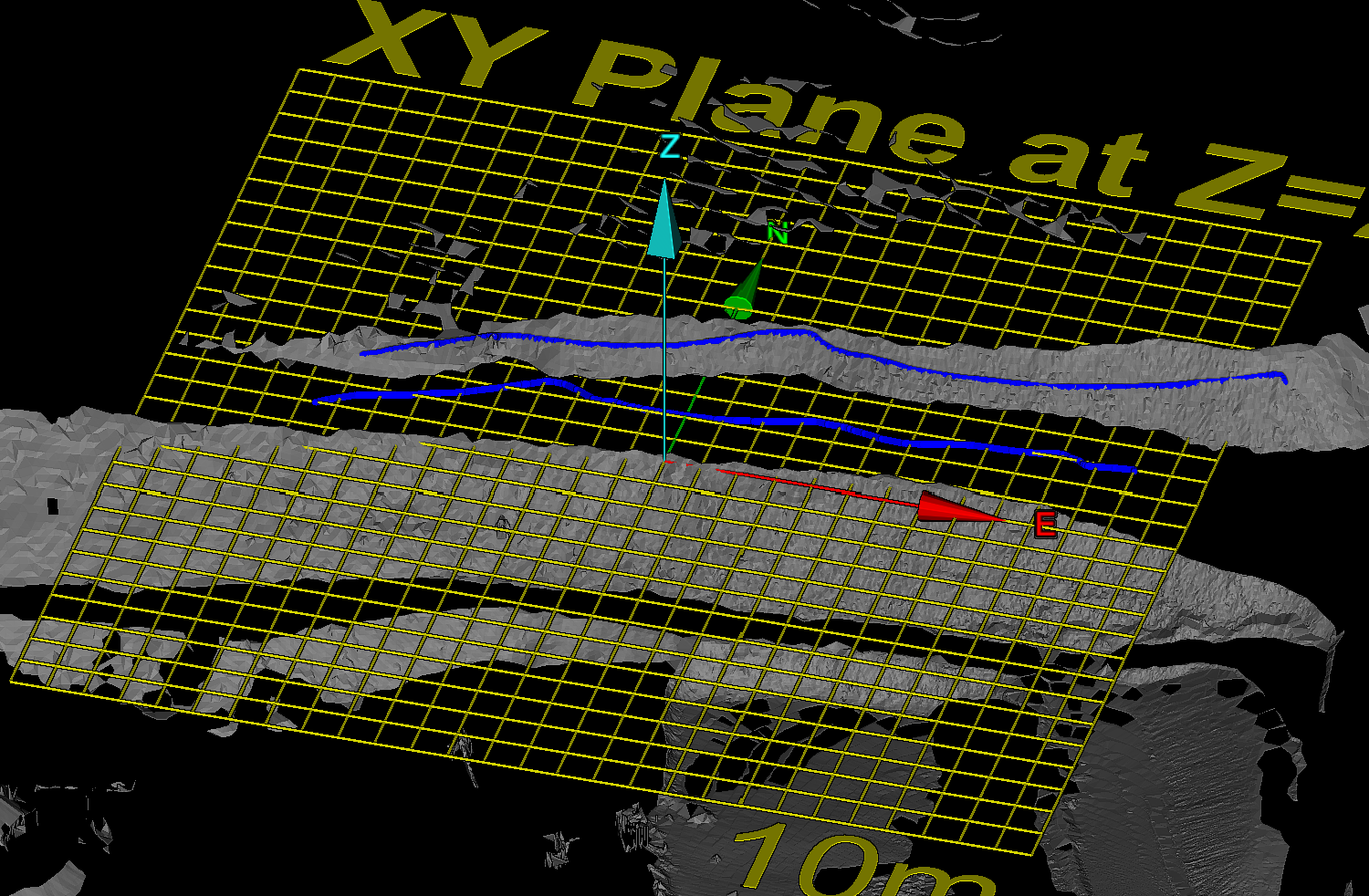
Examples of freehand lines on an object (green) and on the action plane (blue). |
-
On the Create tab, in the Draw group, select
 Freehand Polygon from the Polygon drop-down list.
 -
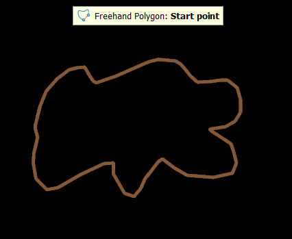
Either enter a specific location for a start point in the status bar or pick a spot where the polygon will begin, release the mouse button, then draw the polygon.

-
Left-click or right-click to complete the polygon.
-
Press Esc or click
(Cancel) in the status bar to exit the tool,
otherwise continue creating new lines.
Rectangle
The Rectangle tool (Alt+[) enables you to draw a rectangle anywhere on the action plane.
To draw a rectangle ![]() , follow these steps:
, follow these steps:
-
On the Create tab, in the Draw group, select
 Rectangle from the Polygon drop-down list.
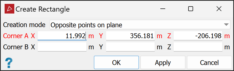
The Create Rectangle tool panel will appear. The panel allows manual input of corner coordinates.
-
From the Creation mode drop-down list, select from the following and draw the rectangle:
-
Opposite points on plane: Select two points as opposite corners. The rectangle will be drawn between these, with its sides aligned with the axes.
-
Three points: Select two points to define adjacent corners and a third to define the length of the perpendicular sides. The fourth side is added automatically.
-
Opposite points and direction: Select points as opposite corners. Move the mouse around and click to set the rectangle's orientation.
Note: Opposite points on plane always creates rectangles on the action plane. Set up the action plane in the required position and orientation before drawing the rectangle.
-
-
Click Apply to continue creating rectangles or OK to accept and exit the tool.
Note: After you finish the rectangle and exit the tool, the rectangle is detached from the action plane. You can move it as required anywhere in 3D space.
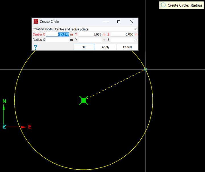
Circle
The Circle tool (Alt+0) enables you to draw a circle anywhere on the action plane.
To draw a circle ![]() , follow these steps:
, follow these steps:
-
On the Create tab, in the Draw group, select
 Circle from the Polygon drop-down list..
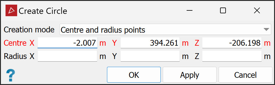
The Create Circle tool panel appears.
-
From the drop-down list, select a Creation mode, and proceed accordingly:
-
Centre and radius points: Select two points. The first will be the centre, the second will set the radius.
-
Opposite diameter points: Select two points on the circumference. The mid-point between them will be the centre.
-
Three radius points: Select three points. The circle will be drawn through all three.
-
Two points and radius: Select two points on the circumference and the enter the radius. You can use the mouse to set the radius.
-
Within triangle: Select three points to define a triangle. The circle is drawn inside the triangle, touching all three sides.
-
Within square: Select two points to define the size and orientation of a square. The circle will be drawn inside the triangle, touching all four sides.
-
Within rectangle: Select two points to define the size and orientation of a rectangle. The circle will be drawn inside the rectangle, touching the middle of the two longer sides.
Note: Centre and radius points and Opposite diameter points always create circles on the action plane. Set up the action plane in the required position and orientation before drawing the circle.
-
-
Click Apply to continue creating circles or OK to accept and exit the tool.
Note: After you finish the circle and exit the tool, the circle is detached from the action plane. You can move it as required anywhere in 3D space.
Tip: Create circles
while in action plane top view ![]() , or use snap modes to ensure the
circles are created in the intended locations. See Snap Modes.
, or use snap modes to ensure the
circles are created in the intended locations. See Snap Modes.
