Grade Control Polygons
This tool generates optimal block classifications and polygon networks from a block model slice.
On the Block menu, click on Grade Control Polygon to display the following interface.
Specification file ( *.gco.spec )
Use the drop-down list to select the specification file if it is in the current working folder, or click the Browse icon to load a file from another location.
If this is a new project, enter the name for the new specification file.
Scenario ID
Use the drop-down list to select the ID file, or create a new one by clicking the New icon.
-
 New
New -
 Delete
 -
 Save
Save -
 Save as
Resetting all values to the default state can be done in two ways:
-
Click the Scenario ID New icon
-
Click the Scenario ID Delete icon
This will reset all values in the Grade Control Optimiser GUI and reset all the values in the specification file. The only entry that will not be reset is the block model. However, the block model is not stored in the specification file.
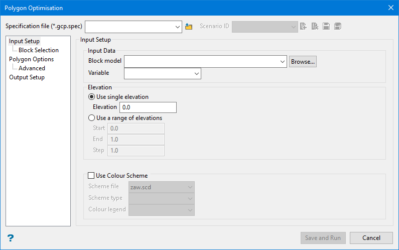
Input Setup
Block Model
Select the model that will be used as input.
Elevation
Enter the elevation in the block model to optimise and create polygons. The elevation should intersect the block model. This is the elevation to reclassify. Enter either a single elevation level, or use a range of elevations.
Use colour scheme
Select this checkbox to colour by using a scheme. A default scheme file and type is entered automatically, these can be altered. Select the file, type and colour legend from the drop down lists.
The colour schemes can be edited using the Analyse > Legend Editor option. Please note that if you select a 'Device_Colour' scheme type, the range of colours will be stretched over the variable values, similar, but not the same as, the Colour by spectrum option. Also, alpha legends are not fully supported.
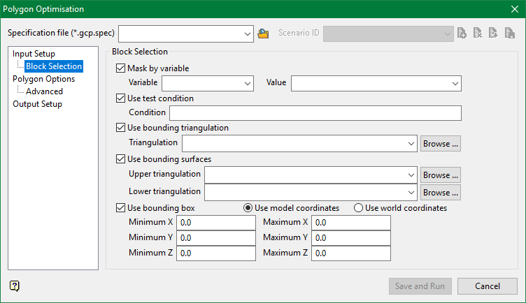
Block Selection
-
Mask by variable
Select the Mask by variable checkbox to restrict the blocks by a block model variable. You will need to select the variable and value to mask by from the Variable and Value drop-down lists.
Example: To restrict blocks to those where Material equals Ore, select Material as the variable and
Oreas the value. The block model variable may be numeric, such as the grade variable Au or character, such as Geology variables. -
Use test condition
Select the Use test condition checkbox to use a further constraint upon a numeric block model variable and enter the condition in the Condition field. The maximum size of the condition is 132 alphanumeric characters.
Refer to the appendix, Operators and Functions, for a full list of available operators and functions.
Example: To select only blocks that have an iron value greater than 10.0, you would select the Use condition checkbox and enter
Fe GT 10.0in the Conditions field. -
Use bounding triangulation
Select the Use bounding triangulation checkbox to restrict the blocks by a triangulation. Select the bounding triangulation to use from the Triangulation drop-down list, or click Browse... to select a triangulation from a location other than your working directory.
Note: This option is not applicable to open or 2D triangulations.
- Use bounding surfaces
Select the Use bounding surfaces checkbox to restrict the blocks by bounding surfaces. Select triangulations from the Upper triangulation and Lower triangulation drop-down lists, or click Browse... to select triangulations from a location other than your working directory.
-
Use bounding box
Select the Use bounding box checkbox to restrict the blocks by a box. Choose either Use model coordinates or Use world coordinates, then enter the minimum and maximum X, Y, and Z coordinates as opposite vertices of the bounding box.
Note: If the block model origin is set at 0,0,0, then select Use world coordinates for the minimum and maximum X, Y, and Z coordinates. If the block model origin is set at real world coordinates, then enter coordinates for the bounding box that are offset a certain distance from the origin. The distance of offset will be determined by the dimensions of your bounding box. It will be the distance to the minimum and the distance to the maximum X, Y and Z from the origin of the block model.
Polygon Options
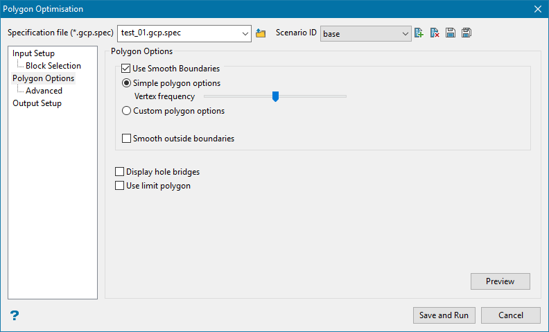
Use Smooth Boundaries
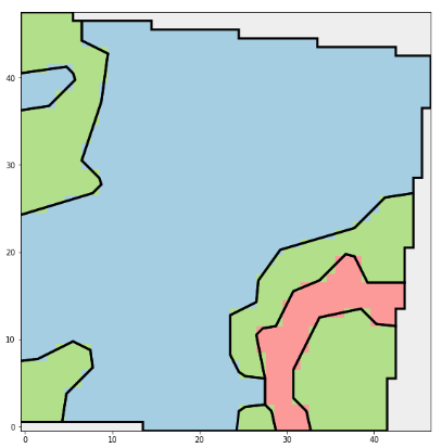
The polygon generation in this option is designed to approximate polygons that are drawn by hand, that is they will not directly follow the block boundaries but instead follow the general character of the block model variable.
If smooth boundaries are not used the polygons will be like this:
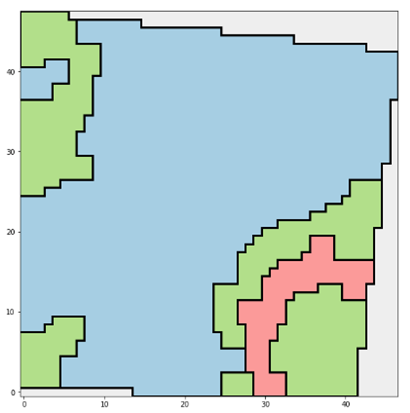
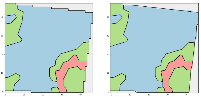
As opposed to this, if smooth boundaries are used:
Vertex frequency
If the slider is to the left there will be fewer vertices in the result polygons, and more blocks will be misclassified. If the slider is to the right there will be more vertices in the result polygon and fewer blocks will be misclassified.
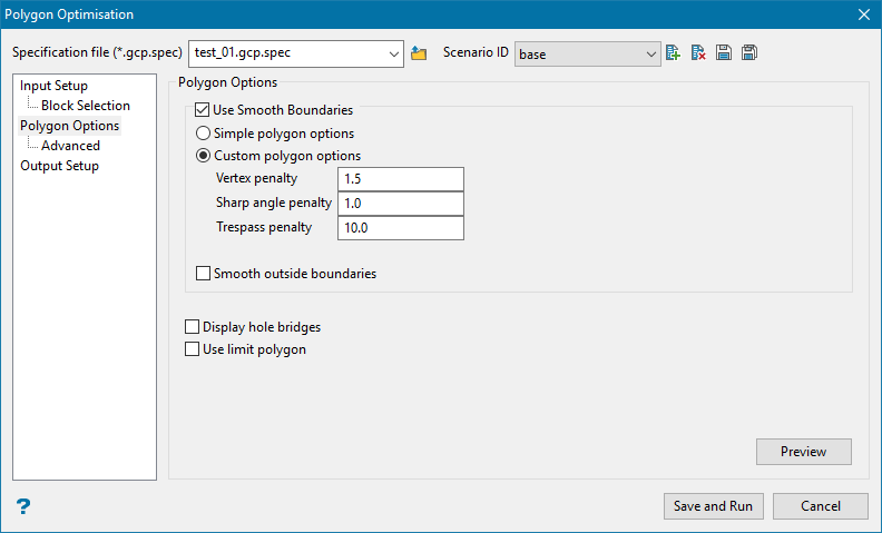
Custom polygon options
The smooth boundaries are generated by an optimiser that attempts to minimize three main penalties.
The actual values do not matter in themselves - they only matter relative to one another.
Vertex penalty
A penalty that the polygon optimiser must pay for introducing an additional vertex.
Sharp angle penalty
A penalty the polygon optimiser pays for introducing a sharp angle between segments. The penalty is less for obtuse angles and increases linearly up to 80 degrees when the penalty is at its maximum.
Trespass penalty
The main penalty for putting a block on the wrong side of the line. This is the main opposing force to the vertex penalty, and as blocks are misclassified it warrants introducing additional vertices.
Smooth outside boundaries
On the boundary of the block selection by default the optimiser uses non-smooth blocky polygon. When this is selected the optimiser will instead smooth those regions as well, like this:
Display hole bridges
This allows you to select the visibility of bridges in output polygons. It will create the constrained delaunay triangulation of the polygon, finding the triangle that is the shortest and connect the hole to the boundary or another hole, and incorporate that bridge.
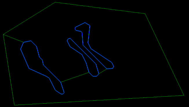
Use limit polygon
If this option is selected, the tool will prompt you to select a limit polygon before saving the results. The polygons generated by the tool will be intersected with the limit polygon.
Note: This specific option is not available when running the tool via GCOPT.EXE.
Preview
This button will calculate the result polygons and display them on the screen without closing the panel to facilitate iterating on the parameters.
Advanced
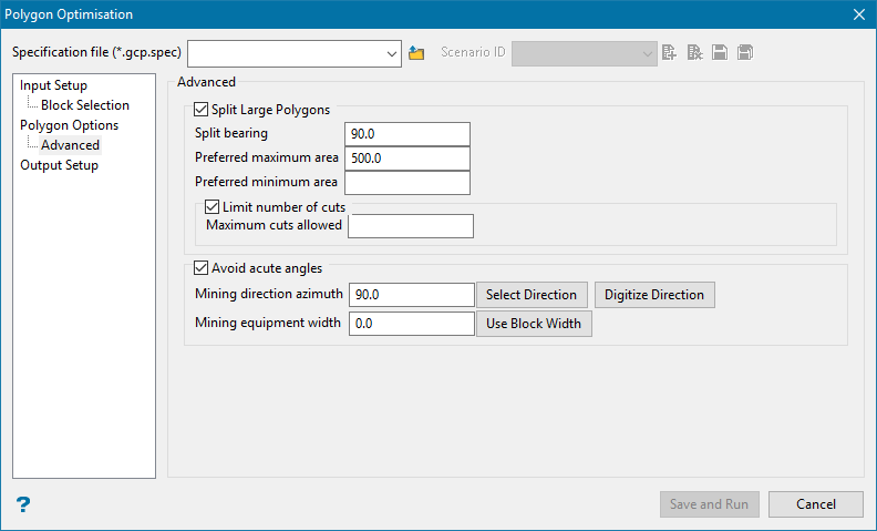
Advanced
Split Large Polygons
An optional post process to split large polygons generated by the tool.
Split bearing
The bearing of the splitting line(s).
Preferred maximum area
The preferred maximum area of the result polygons, that is if the area of the polygon is more than this it will be split into possibly multiple pieces.
Preferred minimum area
The optional preferred minimum area of the result polygons. If a split would generate a polygon that has an area less than this area it will not be split. This is in opposition to the preferred maximum area, and takes precedence.
Example: If a polygon has an area of 590, the preferred maximum area is 200 and the preferred minimum area is blank, the polygon will be split into three with an area of 196.66.
However if the polygon has an area of 210, the preferred maximum area is 200 and the preferred minimum area is 150, the polygon will not be split. Because the split would create polygons of area 105 which is less than 150.
Avoid acute angles
Use this option to make sure that you do not have any acute angles in the direction you are mining by using a vector to indicate the direction or a 0-360 degree bearing.
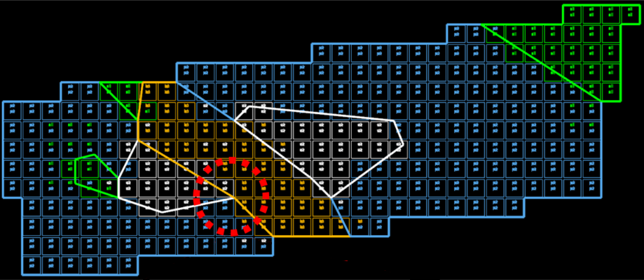
Figure 1: If the blocks are mined from east to west, then they can easily be mined by a shovel or loader.
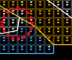
Figure 2: However, if the blocks were mine in the opposite direction (west to east), the shovel or loader would be facing an acute angle and it would be impossible to mine as designed.
Mining direction azimuth
Enter an azimuth, use Select Direction to use a pre-existing line, or use Digitize Direction to create the line dynamically by two points.
Mining equipment width
Enter a mining equipment width, or use the block width of your selected block model by clicking Use Block Width.
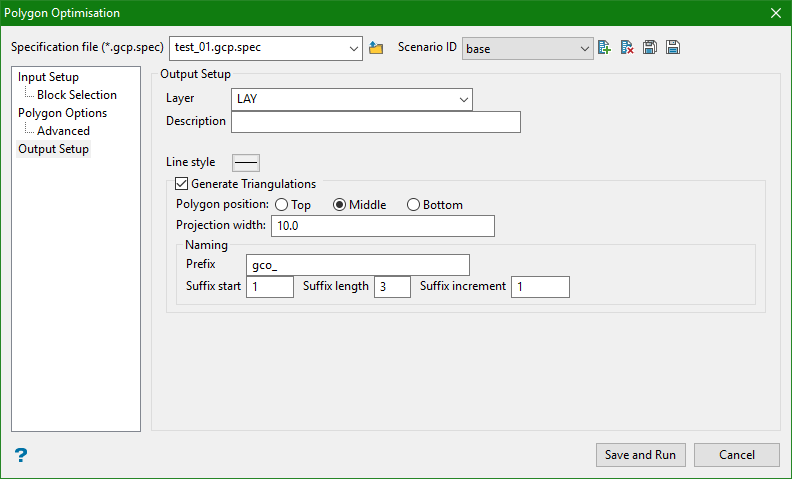
Output
Layer
Layer for result polygons, will be created if it does not exist.
Description
Description of result layer.
Line style
Line style of result polygons.
Generate Triangulations
Select this option if you would like solids created using the output polygons.
Polygon position
Indicate whether you want to polygon to be used as the top, middle, or bottom of the solid. The projection will start from this location.
If the polygon position has been set for the middle, then the distance projected in each direction will be half of the projection width.
Example: A projection width of 10 metres will create a solid that is 10 metres wide with the polygon located in the middle, showing 5 metres on each side.
Projection width
Enter the total width for the new solid.
Naming
Naming the new solids will be done by combining a prefix, which will be used at the beginning of the name for every shape, and a suffix, which will be an incremental number sequence running from the starting suffix number and continuing until all the shapes have been created.
Prefix
Enter a phase, code, or name to act as a name for each shape.
Suffix start
Enter a starting number to begin the sequence.
Suffix length
Enter the character length allotted for the number sequence.
Suffix increment
Enter the incremental step that will be used between each name.
Results using the entries on the panel image above would be:
gco_001.00t
gco_002.00t
gco_003.00t
gco_004.00t
