Create Macro
Use this option to create a macro file for block projections.
The macro file consists of commands that specify block projection parameters. These commands are either operational or instructional. Operational commands perform an operation on a block while instructional commands tell the projection how it is to be done. The commands that can be generated through the option are as follows:
| Table 1 - Instructional Commands | ||
| Instructional Commands | Description | Qualifiers |
|---|---|---|
| CONNECT_CORNER | Specifies that lines be drawn connecting the corners of the blocks | |
| LIMIT | Specifies the topography surface. This is derived from the Set Up option | /SURFACE /STOP_AT_LIMIT |
| STRAIGHT_FACE | Specifies that the face for each projected block remains straight in plan | |
| Table 2 - Operational Commands | ||
| Operational Commands | Description | Qualifiers |
|---|---|---|
| BERM | Takes the current block and berms it | /SURFACE /ALONG /WIDTH /WALL /COLOUR |
| PROJECT | Takes the current block and projects it to a surface. The surface is derived from the Set Up option (upper seam) | /SURFACE /BATTER /WALL /COLOUR |
| REGISTER | Registers a block to a surface. The surface is derived from the Set Up option (lower seam) | /SURFACE /INTERPOLATE /COLOUR |
By default, block projections are done from the bottom seam up, that is, vertical, upward projections. To project downwards, you will need to edit the macro file and incorporate the /Down qualifier. To project horizontally, edit the file and incorporate the /Horizontal qualifier.
Use the Edit Macro option to edit the macro files. A list of all available commands and qualifiers is provided in Appendix C.
Instructions
On the Open Pit menu, point to Benching and Batters, then click Create Macro.
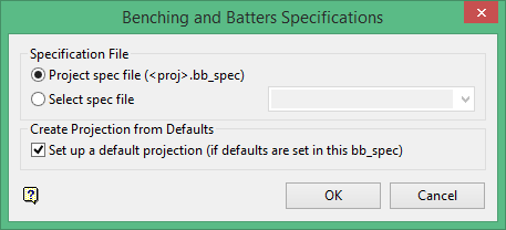
Project spec file
Select this option to create a new benching and batters specification (<proj>.bb_spec) file.
Select spec file
Select this option to choose an existing specification file from those in the current working directory.
Set up a default projection (if defaults are set in this bb_spec)
Select this option to use the default preferences file if defaults are set in this bb_spec.
Click OK.
The Projection Macro File panel displays.
Projection macro file name
Enter the name of the macro projection file using up to 30 alphanumeric characters.
Description
Enter an optional description of the macro projection file.
Projection Macro Defaults
Based on
Select the desired specification file from the drop down listing. All benching and batters specification files in the current working directory will be shown.
Edit Defaults
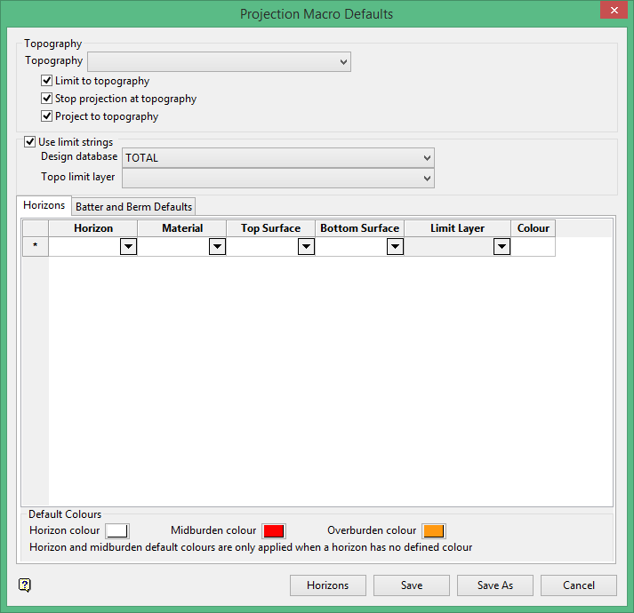
Topography
Select the topography surface that you want to use. The nominated surface can either be a grid or a triangulation. The drop-down list contains all supported grids and triangulations found within your current working directory.
Specify whether you want to limit the projection to the topography, stop the projection at the topography, and/or project to the nominated topography.
Note: If the Stop projection at topography check box is checked, the macro will stop if all the points on the object are on the limiting surface.
Use limit strings
Select this check box if you have a string that limits or bounds the nominated topography. You will need to nominate the design database that contains the limiting layer, and also the topographical layer that contains the limiting string.
Horizons tab
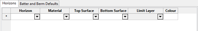
Define the Horizons values for the projection.
Note: The Benching and Batters Set Up panel utilises grid controls, (right-click context menus), that allow you to perform options such as hiding columns, cutting, copying and pasting cells, and inserting and deleting rows. Refer to the Grid Controls section for more information on managing grid information.
Horizon
Select the horizon or seam to be reserved. The full name is <proj><gfi>.<mv>g. The drop-down list contains all available horizons from the nominated topography (.tpg) file.
Material
Select the material of the horizon. The available drop-down list contains all available materials from the nominated topography (.tpg) file.
Top Surface
Select the upper surface of the horizon. The drop-down list contains a listing of the top surface elements available from the nominated topography (.tpg) file.
Bottom Surface
Select the lower surface of the horizon. The drop-down list contains a listing of the bottom surface elements available from the nominated topography (.tpg) file.
Limit Layer
Select the layer containing the previously created seam limits, lease boundaries or pit boundaries. The available drop-down list contains the names of all layers found within the nominated limiting design database. Note the Limit Layer column will be disabled, (unavailable), if the Use limit strings check box has not been checked.
Colour
Select the colour for the chosen horizons. The chosen colour, which is selected from the current colour table, will also be used to colour the strings projected to these surfaces.
Note: The colour used for the topography surface is the colour of the 2D blocks. To change this, you must edit the .bb_spec file and assign the required colour.
Default Colours
Select the default colours for the Horizon, Midburden, and Overburden from the Colours pop-up.
Batter and Berm Defaults
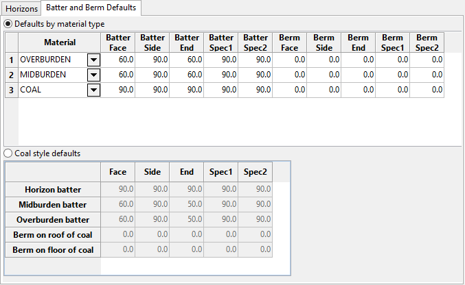
Define the Batter and Berm default values for this projection.
Defaults by material type
The content for this section description is being developed.
Material
Select the material. The drop-down list will contain all available materials from the nominated topography (.tpg) file.
Note: The default values from the nominated topography (.tpg) file will populate the Batter fields. You may change them as desired.
Coal style defaults
Horizon batter
Enter the horizon coal batter angle for the face, side and end wall of the projected block.
Midburden batter
Enter the midburden batter angle for the face, side, and end wall of the projected block, and the Spec1 and Spec2 values.
Overburden batter
Enter the overburden batter angle for the face, side and end wall of the projected block, and the Spec1 and Spec2 values.
Berm on roof of coal
Enter the berm width of the projected block for the Face, Side, End, Spec1, and Spec2 for the horizon batter.
Berm on floor of coal
Enter the berm width of the projected block for the Face, Side, End, Spec1, and Spec2 for the horizon batter.
Block Object Specifications
Maintain straight faces
Select this check box to project the face of each block straight in plan. This has the effect that the specified batter for the face may vary along the length of the face. If this check box is not checked, then the projection will assume that the batters remain constant along the block face. As a result, the projected face line may not be a straight.
Connect corners
Select this check box to draw lines connecting the corners of the projected blocks. This is only effective if maintaining straight faces (see option above). The lines that are created are only for appearance to help viewing the projected block. They have no effect on subsequent volumes calculations. The lines are created as objects in the same layer as the block, and have a common feature name which means that they can be deleted by selecting the feature category using the Design > Object Edit > Delete option.
Save batter and berm values with strip blocks
Select this check box to replace the default W-tag values with those that reflect the macro command that is about to be processed.
For example: If an object is to be bermed next, then it will set each segment of the object that is about to be bermed with the berm distance as defined for that part of the object in the macro.
Note: Using this option may slow down a large run.
Limiting surface
This section to chose the seams (surfaces) to project to (derived from the Set Up option), whether to project to the topography (also derived from the Set Up option), limit the projection to the topography or to stop the projection at the topography.
Stop projection at topography
If this check box is selected, then the macro will stop if all the points on the object are on the limiting surface.
Surface name
Select the surface name.
Limit to surface
Limit to surface will project to the topography surface instead of a seam surface when a block is projected to both a seam surface and the topography at the same time.
Stop projection at surface
Select this check box to ensure that once all points in a polygon have been projected to topography, projections stops. This is useful when a polygon is projected in an eroded area where topography may lie below the uppermost coal seam grid.
Tolerances
Minimum distance tolerance
Enter a minimum distance tolerance or use the default setting. The maximum distance allowed is 500 meters.
How it works
In Diagram 1 below, 400 meters is the distance of the segment, and the values in red (350 and 450 meters) are the values used as the Minimum distance tolerances. In the top example, since the segment is larger than the minimum distance tolerance of 350 meters, it is kept. In the bottom example, however, since the segment is less than the minimum distance tolerance of 450 meters, it is not kept.
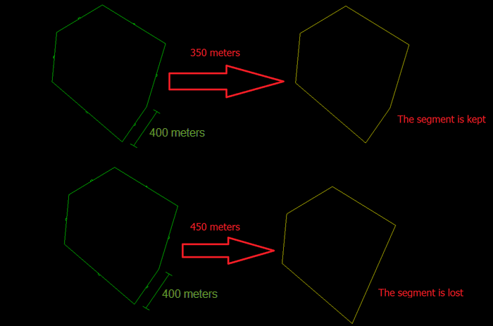
Diagram 1
Minimum angle tolerance
Enter a minimum distance tolerance or use the default setting.
How it works
This parameter is used to remove acute, internal angles smaller than the entered value. In Diagram 2 below, 88 degrees is the internal angle in the corner, and the angle in red (40 and 90 degrees) are the values used as the minimum angle tolerance. In the top example, the corner showing an angle of 88 degrees is greater than the minimum angle tolerance, therefore it is kept. However, in the example on the bottom, the corner showing an angle of 88 degrees is less than the minimum angle of tolerance. Therefore, it is removed. Note that the two line segments making up the angle (highlighted by the dashed yellow lines) are removed and a new segment is created that connects the two adjacent vertices.
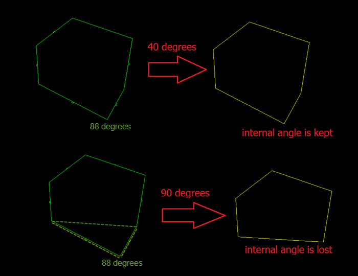
Diagram 2
Parallel angle tolerance
Enter a minimum parallel angle tolerance or use the default setting.
How it works
This parameter is used to define if two lines are parallel. If two lines are found to be parallel, they are combined to one. The smallest accepted value is 0 degrees. The default is 5 degrees, and there is no limit to the maximum, but the process will fail if you put an angle close to 90. In Diagram 3 below, the top example shows a line segment (highlighted by a dashed yellow line) with angle of 18 degrees. Since this is greater than the minimum parallel angle tolerance of 5 degrees. Therefore, the angle remains in place. However, in the lower example, the same 18 degree angle is less than the minimum parallel angle tolerance of 20 degrees. Therefore, the angle is removed.
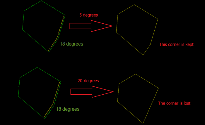
Diagram 3
Load Defaults
The Load Defaults option to load a previously created default specification file.
Projection Direction
Select the direction for the projection, up or down.
Click Save.
The projection macro information displays in the Report Window.
