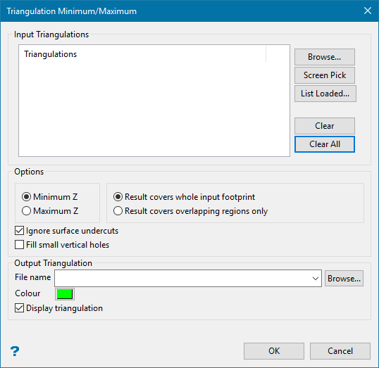
Minimum/Maximum
Use the Minimum/Maximum option to create a triangulation surface that follows the topography of a nominated collection of triangulations. Both surfaces and solids can be used. This functionality helps to model stage surfaces in mine planning.
Instructions
On the Model menu, point to Triangle Utility, and then click Minimum/Maximum.
Input Triangulations
Browse
Click this button to display the Open panel, then use it to select the triangulations you wish to evaluate.
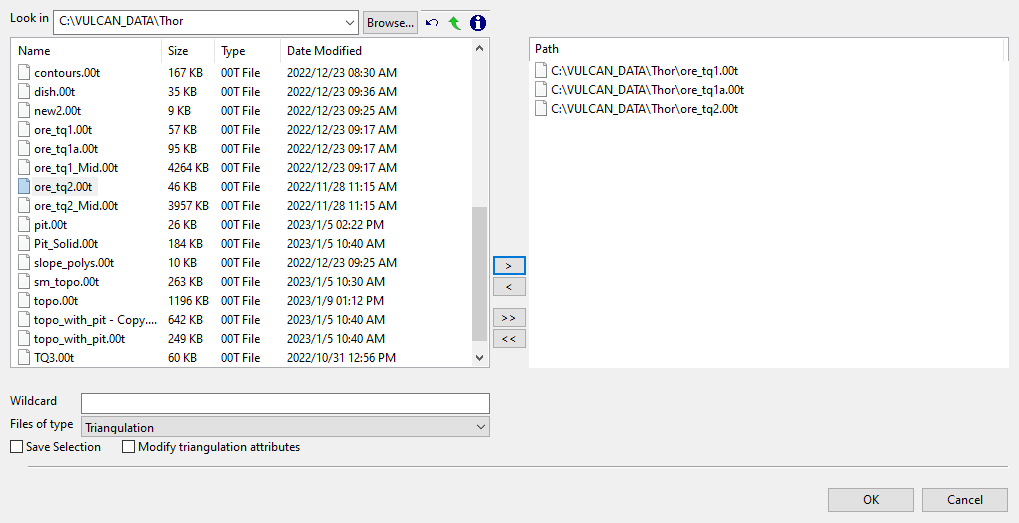
File Selection
Browse for files using the Browse... button, or use the interface showing the available grid files in the current working directory.
Click on the names of the files you want to select. Use the  buttons to go to the last folder visited, go up one level, or change the way details are viewed in the window.
-
To highlight multiple consecutive files in the list, hold down the Shift key and click the first and last file names in that section of the list.
-
To highlight multiple non-consecutive files, hold down the Ctrl key while clicking the file names.
Move the items to the selection list on the right side of the panel.
-
Click the
 button to move the highlighted items to the selection list on the right.
 -
Click the
 button to remove the highlighted items from the selection list on the right.
 -
Click the
 button to move all items to the selection list on the right.
 -
Click the
 button to remove all items from the selection list on the right.
Wildcard
Enter the text to use as a filter, then press Enter. Use * for multiple characters or % to replace a single character.
Example: For example, with topo_* used as a wildcard, the result might be topo _area2_aerial, topo _min, or topo _with_pit.
Screen Pick
Click this button to select the triangulations from the screen.
List Loaded
Click this button to display a list of triangulations that are loaded on the screen in the Select Triangulations panel.
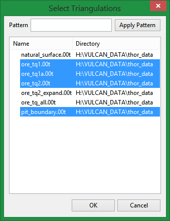
You may pick multiple triangulations from the list by holding Ctrl and selecting with the mouse.
Pattern
Use this to enter any wildcard combinations. Click Apply Pattern to highlight the results in the list.
Click OK to finalise your selection and return to the main panel.
Clear
Click this button to remove the highlighted triangulation from the list. You may pick multiple triangulations from the list by holding Ctrl and selecting with the mouse.
Clear All
Click this button to remove all triangulations from the list.
Options
Minimum Z / Maximum Z
Select whether you want to create a new triangulation based on either the minimum or maximum elevation found within your area of interest.
Result covers whole input footprint
Select this option if you want the new triangulation to extend over the entire area covered by all the triangulations in your list.
Result covers overlapping regions only
Select this option if you want the new triangulation to only extend those areas where there is overlap of the triangulations.
Output Triangulation
File name
Enter the name of the resulting triangulation surface. The resulting triangulation will be stored in the current working directory.
Colour
Click on the coloured box to display the colour palette, then select the colour for the new triangulation.
Display triangulation
Pattern
Use this to enter any wildcard combinations. Click Apply Pattern to highlight the results in the list.
Click OK to finalise your selection and return to the main panel.
Clear
Click this button to remove the highlighted triangulation from the list. You may pick multiple triangulations from the list by holding Ctrl and selecting with the mouse.
Clear All
Click this button to remove all triangulations from the list.
Options
Minimum Z / Maximum Z
Select whether you want to create a new triangulation based on either the minimum or maximum elevation found within your area of interest.
Result covers whole input footprint
Select this option if you want the new triangulation to extend over the entire area covered by all the triangulations in your list.
Result covers overlapping regions only
Select this option if you want the new triangulation to only extend those areas where there is overlap of the triangulations.
Ignore surface undercuts
When the surfaces are scanned in detail, there seem to appear negative slopes or undercuts which are not that significant in the scale of whole model. Generally, this detailed analysis requires longer computational time.
Select this option to discard those insignificant undercuts and consequently make the computation faster. By default, this option is selected assuming that the surfaces used are gridable.
Fill small vertical holes
When the surface undercuts are ignored, there is possibility of small vertical holes appearing in the model in place of those undercuts. Select this option to fill those holes.
Note: Sometimes, the holes might not get filled by this option. In that case, just deselect Ignore surface undercuts option.
Output Triangulation
File name
Enter the name of the resulting triangulation surface. The resulting triangulation will be stored in the current working directory.
Colour
Click on the coloured box to display the colour palette, then select the colour for the new triangulation.
Display triangulation
Select this option to automatically display the new triangulation after it has been created.
Click OK.
The triangulation is then created.
