Cost Benefit Analysis
Use Cost Benefit Analysis to analyse an ore body based on predefined variables, such as recovery, mining cost, dilution etc., and return whether or not it should be mined.
The variables used to perform the analysis are configured through the Underground > Development > Set Up option. Once configured, these variables will be saved in your Underground Development preferences file (UGDEVS.prefs). This file will be stored in your user profiles area, for example 'C:\Documents and Settings\<user name>'. If the preferences file does not exist, then the Set Up option can be used to create one.
Instructions
On the Underground menu, point to Analyse, and then click Cost Benefit Analysis to display the Cost Benefit Analysis Block Model Variables panel.
The Cost Benefit Analysis Block Model Variables panel has two tabs:
- General
- Block Selection
General tab
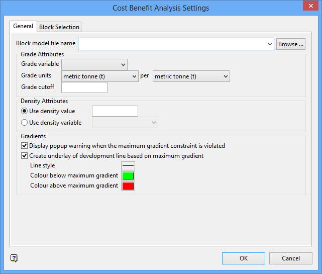
Block model Block model file name
Select the block model that you want to use. The drop-down list contains all block models found in the current working directory. Click Browse to select a file from another location.
Grade Attributes
Grade variable
Select a grade variable. The chosen variable cannot be a text variable. The drop-down list contains all variables found in the chosen block model file.
Grade units
Select the applicable grade unit and the desired unit measurement (for example per metric tonne, per kilogram, per ounce, etc.) from the drop-down boxes.
Grade Cutoff
Enter appropriate cutoff value.
Density Attributes
The density value can either be manually entered or you can use the values contained in a nominated block model variable.
Gradients
Display popup warning when the maximum gradient constraint is violated
Select this checkbox to display a notification if any line segment along the chosen development line is above the maximum gradient constraint. The gradient test used degree values. This checkbox is selected by default.
Note: The maximum gradient constraint is defined in Underground > Development > Set Up.
Create underlay of development line based on maximum gradient
Select this checkbox to create an underlay of the development line.
You can choose the underlay line style, and the colours below and above the maximum gradient.
Note: Underlays are always displayed behind loaded design objects. If an underlay exactly overlaps a design object (such as the ramp object), you will need to remove the design object to see the underlay.
Block Selection tab
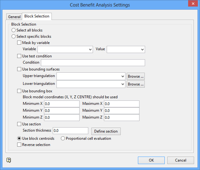
Either all blocks or specific blocks can be selected. If you select Select specific blocks by, then you must enter one or more of the following selection criteria:
Mask by variable
Select the Mask by variable checkbox to restrict the blocks by a block model variable. You will need to select the variable and value to mask by from the Variable and Value drop-down lists.
Example: To restrict blocks to those where Material equals Ore, select Material as the variable and Ore as the value. The block model variable may be numeric, such as the grade variable Au or character, such as Geology variables.
Use test condition
Select the Use test condition checkbox to use a further constraint upon a numeric block model variable and enter the condition in the Condition field. The maximum size of the condition is 132 alphanumeric characters.
Refer to the appendix, Operators and Functions, for a full list of available operators and functions.
Example: To select only blocks that have an iron value greater than 10.0, you would select the Use condition checkbox and enter Fe GT 10.0 in the Conditions field.
Use bounding triangulation
Select the Use bounding triangulation checkbox to restrict the blocks by a triangulation. Select the bounding triangulation to use from the Triangulation drop-down list, or click Browse... to select a triangulation from a location other than your working directory.
Note: This option is not applicable to open or 2D triangulations.
Select the Use bounding surfaces checkbox to restrict the blocks by bounding surfaces. Select triangulations from the Upper triangulation and Lower triangulation drop-down lists, or click Browse... to select triangulations from a location other than your working directory.
Use bounding box
Select the Use bounding box checkbox to restrict the blocks by a box. Choose either Use model coordinates or Use world coordinates, then enter the minimum and maximum X, Y, and Z coordinates as opposite vertices of the bounding box.
Note: If the block model origin is set at 0,0,0, then select Use world coordinates for the minimum and maximum X, Y, and Z coordinates. If the block model origin is set at real world coordinates, then enter coordinates for the bounding box that are offset a certain distance from the origin. The distance of offset will be determined by the dimensions of your bounding box. It will be the distance to the minimum and the distance to the maximum X, Y and Z from the origin of the block model.
Use section
Select this checkbox to restrict the blocks by a section plane. You will need to enter its associated thickness. The blocks that are within this thickness will be selected.
The section plane can be selected by line, points or grid coordinates. This information is entered through the Section Plane panel, which is displayed once the Block Selection panel has been completed. You may also select the Use block centroids and use it with this restriction.
Use block centroids
Select this option to include blocks if the block centroid is within the region. The entire block will be included.
Proportional cell evaluation
Select this option to include those block that touch the region, and evaluate reserves according to the proportion of the block's volume that lies within the region. Proportional cell evaluation calculates and reports the exact proportion of a block within a solid triangulation. When selecting blocks, all blocks that touch the region are selected.
Reverse selection
Select this checkbox to select outside the specified regions. See the description of the Variable field. This checkbox will be disabled when the Cut and fill surfaces checkbox is in use.
This checkbox is only available when using the Advanced Reserves Editor, or when limiting the block selection by a bounding box, triangulation or surfaces.
Select the target triangulation from the screen. If only one triangulation is loaded, then it will be selected automatically.
Once the target triangulation has been nominated, you will be prompted to indicate the start and end of the development. The development, which consists of two points, should be indicated using the available snapping tools. You will need to confirm the development once it has been digitised onscreen.
The necessary calculations are then performed. The report information will be outputted to the Report Window and, if applicable, the nominated output files.
