Distance
Use this option to calculate the distance from each block in a block model to the nearest boundary of a triangulation, block with a particular value assigned to a variable, nearest intercept of a drillhole, the nearest point of a polyline, or nearest section of a polyline.
Instructions
In the Block menu, point to Manipulation, then click Distance to display the following interface.
Specification file
Use the drop-down list to select the specification file if it is in the current working directory, or browse for it in another location by clicking the Browse button. You may also create a new file by typing the name of the new file in the textbox.
Scenario ID
Use the drop-down list to select the ID file, or create a new one by clicking the New button.
-
 New
New -
 Delete
 -
 Save
Save -
 Save as
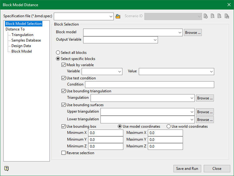
Block Selection
Block model
Use the drop-down list to select the block model if it is in the current working directory, or browse for it in another location by clicking the Browse button.
Output Variable
Select the variable that will store the distance results.
Select all blocks
Select all blocks in the chosen block model.
Select specific blocks
Select only the block that meet the criteria set by the following conditions:
Use block centroids
Select this option to include blocks if the block centroid is within the region. Note the entire block is included.
Proportional cell evaluation
Select this option to include those blocks that touch the region, and evaluate reserves according to the proportion of the block's volume that lies within the region. Proportional cell evaluation calculates and reports the exact proportion of a block within a solid triangulation. When selecting blocks, all blocks that touch the region are selected.
-
Mask by variable
Select the Mask by variable checkbox to restrict the blocks by a block model variable. You will need to select the variable and value to mask by from the Variable and Value drop-down lists.
Example: To restrict blocks to those where Material equals Ore, select Material as the variable and
Oreas the value. The block model variable may be numeric, such as the grade variable Au or character, such as Geology variables. -
Use test condition
Select the Use test condition checkbox to use a further constraint upon a numeric block model variable and enter the condition in the Condition field. The maximum size of the condition is 132 alphanumeric characters.
Refer to the appendix, Operators and Functions, for a full list of available operators and functions.
Example: To select only blocks that have an iron value greater than 10.0, you would select the Use condition checkbox and enter
Fe GT 10.0in the Conditions field. -
Use bounding triangulation
Select the Use bounding triangulation checkbox to restrict the blocks by a triangulation. Select the bounding triangulation to use from the Triangulation drop-down list, or click Browse... to select a triangulation from a location other than your working directory.
Note: This option is not applicable to open or 2D triangulations.
- Use bounding surfaces
Select the Use bounding surfaces checkbox to restrict the blocks by bounding surfaces. Select triangulations from the Upper triangulation and Lower triangulation drop-down lists, or click Browse... to select triangulations from a location other than your working directory.
-
Use bounding box
Select the Use bounding box checkbox to restrict the blocks by a box. Choose either Use model coordinates or Use world coordinates, then enter the minimum and maximum X, Y, and Z coordinates as opposite vertices of the bounding box.
Note: If the block model origin is set at 0,0,0, then select Use world coordinates for the minimum and maximum X, Y, and Z coordinates. If the block model origin is set at real world coordinates, then enter coordinates for the bounding box that are offset a certain distance from the origin. The distance of offset will be determined by the dimensions of your bounding box. It will be the distance to the minimum and the distance to the maximum X, Y and Z from the origin of the block model.
Reverse selection
The entire block is included within the slice (blocks are displayed) by default. Select this checkbox to exclude (not display) the selected blocks within the slice.
Important: Each method is mutually exclusive. This means that if one method is selected, all other methods will be deselected. Only one method can be performed at once. However, the parameters for all methods can be set up and saved in a single specification file.
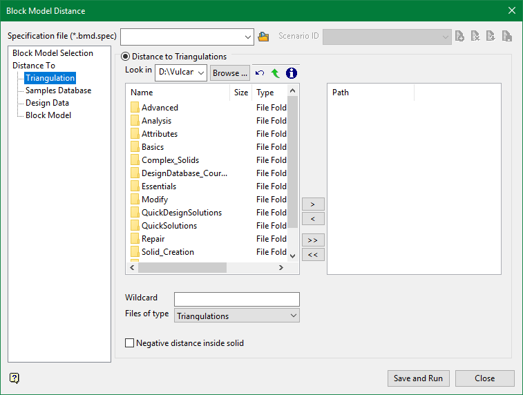
Distance to Triangulations
Select the required triangulation files and add them to the selection list on the right side of the panel.
- Click on the name of the file(s) you want to select.
- To select a triangulation file from another location, click Browse.
- To highlight multiple files that are adjacent to each other in the list, hold down the Shift key and click the first and last file names in that section of the list.
- To highlight multiple non-adjacent files, hold down the Ctrl key while you click the file names.
- Move the files to the selection list on the right side of the panel.
- Click the -> option to move the highlighted files to the selection list on the right.
- Click the >> option to move all the files to the selection list on the right.
- Click the <- option to remove a highlighted file from the selection list.
- Click the << option to remove all files from the selection list.
Wildcard
Enter any characters used as wildcards. Wildcard characters can be an * as well as regular characters. For example, if the topo* were used as a wildcard, the result would be:
-
topo_regional.00g
-
topo_no_pit.00g
-
topo_pit.00g
-
topo_dump.00g
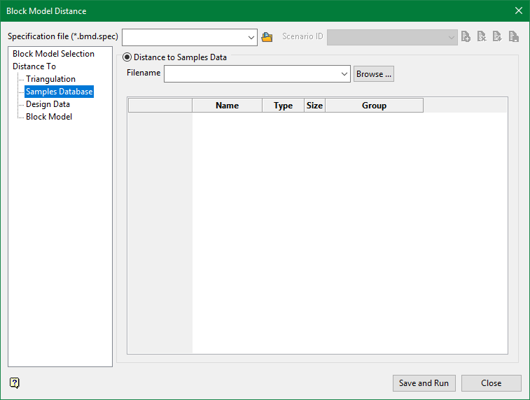
Distance to Samples Data
Filename
Enter the filename or select the file from the drop-down. Click Browse to select a file from a different location.
Name
Automatically populated field showing the name of the field from which the Group name is taken.
Type
Automatically populated field showing the data type of the Name field.
Size
Automatically populated field showing the character limit for the Name field.
Group
Enter the group name. By default a wildcard character is here to include all entries.
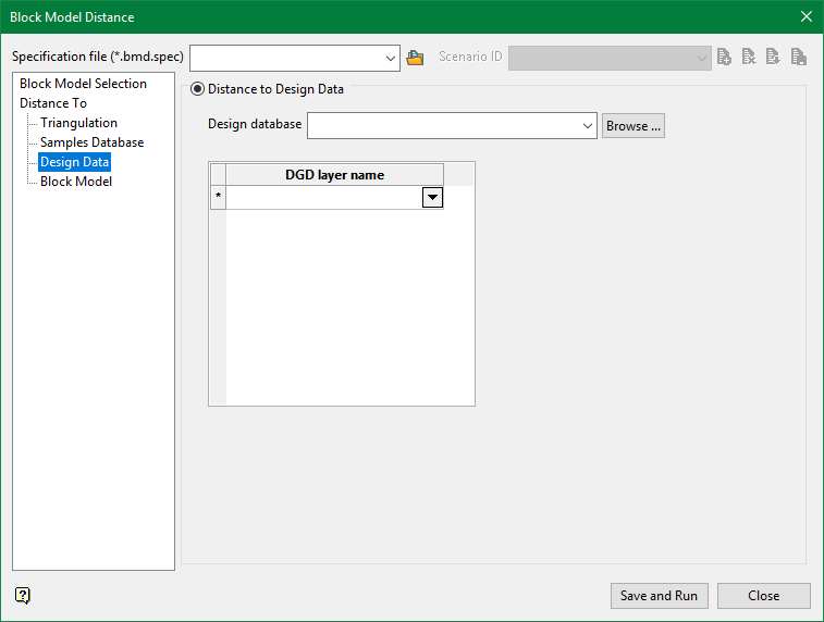
Distance to Design Data
Design database
Select the design database from the drop-down list, or browse for it by click on the Browse button.
DGD layer name
Select the layer from the drop-down list.
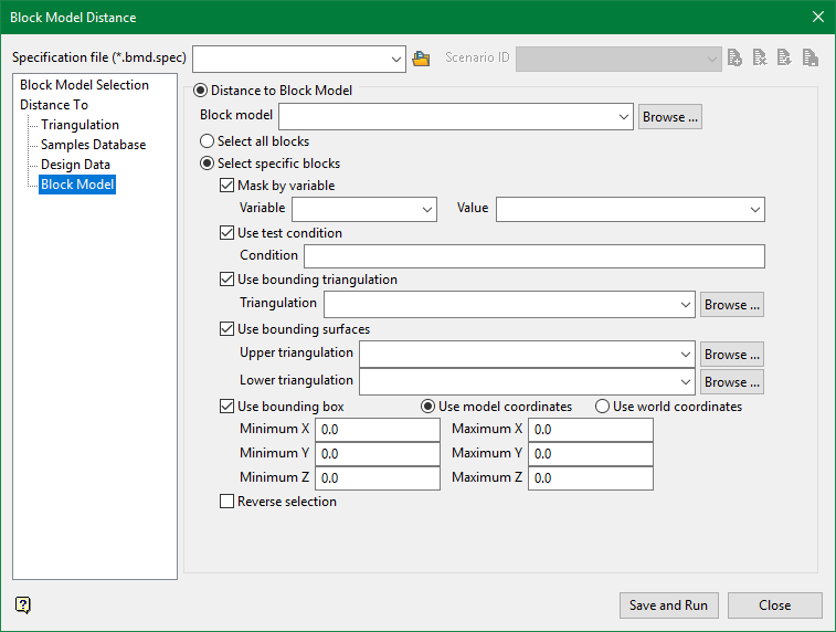
Distance to Block Model
Select all blocks
Select all blocks in the chosen block model.
Select specific blocks
Select only the block that meet the criteria set by the following conditions:
Use block centroids
Select this option to include blocks if the block centroid is within the region. Note the entire block is included.
Proportional cell evaluation
Select this option to include those blocks that touch the region, and evaluate reserves according to the proportion of the block's volume that lies within the region. Proportional cell evaluation calculates and reports the exact proportion of a block within a solid triangulation. When selecting blocks, all blocks that touch the region are selected.
Mask by variable
Select the Mask by variable checkbox to restrict the blocks by a block model variable. You will need to select the variable and value to mask by from the Variable and Value drop-down lists.
Example: To restrict blocks to those where Material equals Ore, select Material as the variable and Ore as the value. The block model variable may be numeric, such as the grade variable Au or character, such as Geology variables.
Use test condition
Select the Use test condition checkbox to use a further constraint upon a numeric block model variable and enter the condition in the Condition field. The maximum size of the condition is 132 alphanumeric characters.
Refer to the appendix, Operators and Functions, for a full list of available operators and functions.
Example: To select only blocks that have an iron value greater than 10.0, you would select the Use condition checkbox and enter Fe GT 10.0 in the Conditions field.
Use bounding triangulation
Select the Use bounding triangulation checkbox to restrict the blocks by a triangulation. Select the bounding triangulation to use from the Triangulation drop-down list, or click Browse... to select a triangulation from a location other than your working directory.
Note: This option is not applicable to open or 2D triangulations.
Select the Use bounding surfaces checkbox to restrict the blocks by bounding surfaces. Select triangulations from the Upper triangulation and Lower triangulation drop-down lists, or click Browse... to select triangulations from a location other than your working directory.
Use bounding box
Select the Use bounding box checkbox to restrict the blocks by a box. Choose either Use model coordinates or Use world coordinates, then enter the minimum and maximum X, Y, and Z coordinates as opposite vertices of the bounding box.
Note: If the block model origin is set at 0,0,0, then select Use world coordinates for the minimum and maximum X, Y, and Z coordinates. If the block model origin is set at real world coordinates, then enter coordinates for the bounding box that are offset a certain distance from the origin. The distance of offset will be determined by the dimensions of your bounding box. It will be the distance to the minimum and the distance to the maximum X, Y and Z from the origin of the block model.
Reverse selection
The entire block is included within the slice (blocks are displayed) by default. Select this checkbox to exclude (not display) the selected blocks within the slice.
