Create Sections
The Create Sections option offers you 5 methods for generating section lines. Section lines are required for profile generation, and thus for volume calculation. They should be placed and spaced in such a way as to produce the best end area volume.
Instructions
On the Open Pit menu, point to Pit Volumes, then click Create Sections.
The Method dialogue box is then displayed. From this box, select a method to create the section lines.
Parallel
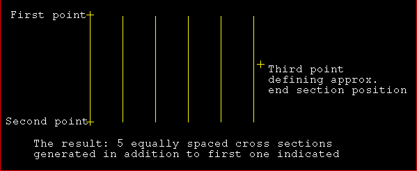
The Parallel method of generating section lines requires you to define a baseline against which the parallel section lines will be created. A third point will then be used to determine the extent of the section lines.
If you selected Parallel, then the following panel will be displayed.
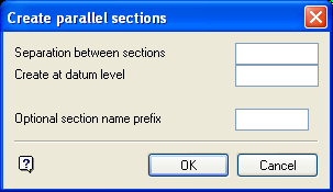
Separation between sections
Enter the distance between the cross sections.
Create at datum level
Enter the datum level. The sections will be generated at the nominated datum level. If a datum level is not specified, then the default Z value will be used instead.
Optional section name prefix
Enter the section name prefix. This can be used for a set of section lines.
For example, if prefix 'A' was used for the six section lines in Diagram 1, then they would be namedA1toA6.
Select OK.
Indicate the start and end point of the first section line. Any of the design entry modes can be used. Once the baseline has been defined, you will then need to indicate the approximate end section position.
Depending on the separation distance specified, the appropriate number of equally spaced cross section lines will then be generated.
Perpendicular
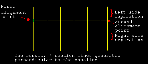
The Perpendicular method of generating section lines requires you to define an alignment line. The section lines will then be created perpendicular to this line.
Indicate the first and second point of the alignment line. Any of the design entry modes can be used.
Once the alignment line has been defined, the following panel is displayed.
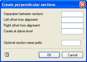
Separation between sections
Enter the distance between the cross sections.
Note The last section line created will coincide with the position of the indicated end point, regardless of whether the 'separation' divides equally into the distance selected or not.
Left/Right offset from alignment
Enter the extent of the section line from the alignment line. The orientation ('left' or 'right') of the offset is determined by "looking" from the first digitised point of the alignment line to the second point as illustrated in Diagram 2.
Create at datum level
Enter the datum level. The sections will be generated at the nominated datum level. If a datum level is not specified, then the default Z value will be used.
Optional section name prefix
Enter the section name prefix. This can be used for a set of section lines.
For example, if prefix 'A' was used for the seven section lines in Diagram 2, then they would be namedA1toA7.
Select OK.
The section lines are then generated.
Easting
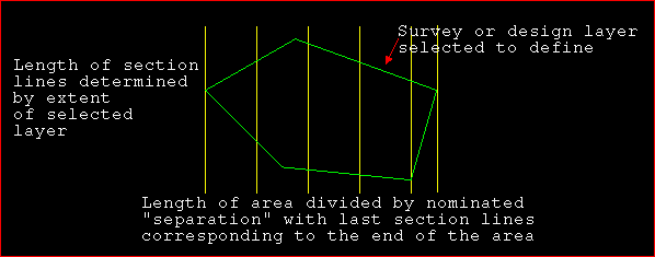
The Eastings method allows you to generate equally spaced section lines at a nominated interval across the area of a selected layer.
Select a major survey or design model. This refers to the survey or design layer over which the section lines are to be generated. Once indicated, the string is highlighted and you will be asked whether or not this is the correct layer.
Upon confirmation, the following panel is displayed.
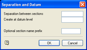
Separation between sections
Enter the distance between parallel cross sections.
Create at datum level
Enter the datum level. The sections will be generated at the nominated datum level. If a datum level is not specified, then the default Z value will be used.
Optional section name prefix
Enter the section name prefix. This can be used for a set of section lines.
For example, if prefix 'A' was used for the six section lines in Diagram 3, then they would be namedA1toA6.
Select OK.
The section lines are then generated. If the area does not divide equally by the nominated separation, then an extra section is inserted to coincide with the end of the area. This is to ensure that the full extent of the layer is covered.
Northing
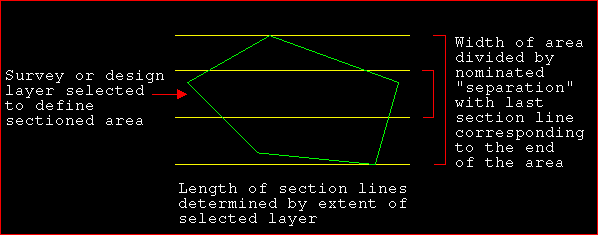
The Northings method allows you to generate equally spaced section lines at a nominated interval across the area of a selected layer (as illustrated in Diagram 4). The only difference between the Northings and Eastings options is that the Northings option generates section lines along northings at the elevation input, instead of generating section lines along eastings at the elevation input.
Select a major survey or design model. This refers to the survey or design layer over which the section lines are to be generated. Once indicated, the string is highlighted and you will be asked whether or not this is the correct layer.
Upon confirmation, the following panel is displayed.
Separation between sections
Enter the distance between parallel cross sections.
Create at datum level
Enter the datum level. The sections will be generated at the nominated datum level. If a datum level is not specified, then the default Z value will be used.
Optional section name prefix
Enter the section name prefix. This can be used for a set of section lines.
For example, if prefix 'A' was used for the four section lines in Diagram 4, then they would be namedA1toA4.
Select OK.
The section lines are then generated. If the area does not divide equally by the nominated separation, then an extra section is inserted to coincide with the end of the area. This is to ensure that the full extent of the layer is covered.
Single
The Single method allows you to generate a single section line at a nominated position across the selected layer.
If you selected Single, then the following panel will be displayed.
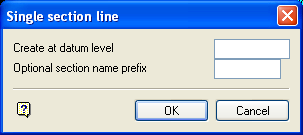
Create at datum Level
Enter the datum level. The sections will be generated at the nominated datum level. If a datum level is not specified, then the default Z value will be used.
Optional section name prefix
Enter the section name prefix.
Select OK.
Indicate the first and second point of the alignment line. Any of the design entry modes can be used. Once the alignment line has been defined, a single section line is generated between the nominated points.
Block Layout
The Block Layout method allows you to generate section lines that are perpendicular to a given strip with the section line separation defined by the block layout along that strip.
If you select Block Layout, the following panel is displayed.
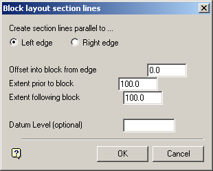
Create section lines parallel to
Select whether the section lines are to be created parallel to either the left or right edge of the strip/block.
Offset into block from edge
Enter the offset value. Section lines will be generated from the specified offset of the block edge. In the diagram below, the left edge has been used.
Extent prior to block
Enter the extent of the section line before a block (see the diagram below).
Extent following block
Enter the extent of the section line following a block This should allow for the number of strips you want to work on.
Datum Level (optional)
Enter the datum level. If not specified, then the section lines will be generated at the default Z level.
Select OK.
Indicate the point from which the mining and block advance directions are to be taken from. You will then need to specify the direction of mining, followed by the direction of block advance.
Once indicated, you will then be asked to select the layer that defines the block layout. After confirming your selection, the section lines are generated.
Long Section
The Long Section option to create a long section line. A long section line differs from a section line in that it may have any number of straight sections. There may only be one long section line per working layer. The XS On LSection option can be used to create a series of perpendicular section lines along the long section alignment.
Once selected, the following panel will be displayed.

Create at datum level
Enter the datum level. The long section line will be generated at the nominated datum level. If not specified, then the line will adopt the default Z value if Indicate mode was used to digitise the line. Otherwise, the line will adopt the appropriate Z value if another digitising mode was used.
Optional longsection name prefix
Enter the long section name prefix. The maximum size of this optional prefix is 5 alphanumeric characters.
Select OK.
Indicate the first and second point of the alignment line. Any of the design entry modes can be used. Once the alignment line has been defined, you will then need to indicate the next point. You can indicate as many points as required.
Once indicated, a line is generated between the nominated points. Cancel when finished indicating points.
Tip: When using Pit Volumes, it is best to ensure that section lines are parallel to each other. We recommend that you don't use single section lines and combinations of section lines when using this option.
