Composite and Model Qualities
Use Coal Compositing to produce a composite for any specific interval down a hole. The composite interval (the structure) can be defined by geology, height, surfaces, or a combination of these. Analytical data can be extracted from multiple databases using depths or samples.
The composites can be output to a standard mapfile, a CSV file or a composite database.
Instructions
On the Grid Calc menu, point to Integrated Stratigraphic Modelling, then click Composite and Model Qualities.
Specifications
Use this section to create or load a Coal Compositing specification file (.ccp). This file is where the changes made on this panel are saved.
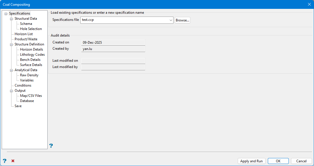
Specification file
Select the Coal Compositing specification file (.ccp) that you want to open. The drop-down contains all of the .ccp files found in the current working directory. Click Browse if this file is not located in the current work area.
Basic Audit details are automatically captured and stored with this file.
Note: If an existing Coal Compositing (.ccp) Specification file does not exist, you can enter the file name and file extension or continue to the Structural Data pane. There is an opportunity to save the specification configuration in the Save pane.
Audit details
These fields are automatically populated if the nominated specification file has any modification history. The Created on/by an Last modified on/by fields are read-only, and cannot be modified.
| Buttons | |
|
Apply and Run |
Click this button to save the entries before performing the compositing run. Once selected, the Coal Compositing interface will be hidden temporarily and the compositing run is performed. If a compositing run is cancelled, you will need to confirm that you want to interrupt the compositing run before the interface can be displayed again. |
|
OK |
Click this button to save all entries before exiting the Coal Compositing interface or moving to the next panel. |
|
Cancel |
Click this button to exit the Coal Compositing interface without saving any settings. |
Structural Data
Use Structural Data to set up the database that contains the structural data.
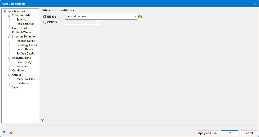
There is an opportunity later to select one or more different databases which contain quality data.
ISIS File
Define the database which will contain the TO and FROM intervals which define the composite. Click Browse if the database is not in current work area.
ODBC Link
It is possible to use an ODBC linked database.
Schema
Once the structural database is defined, database synonyms are used to populate the Schema pane.
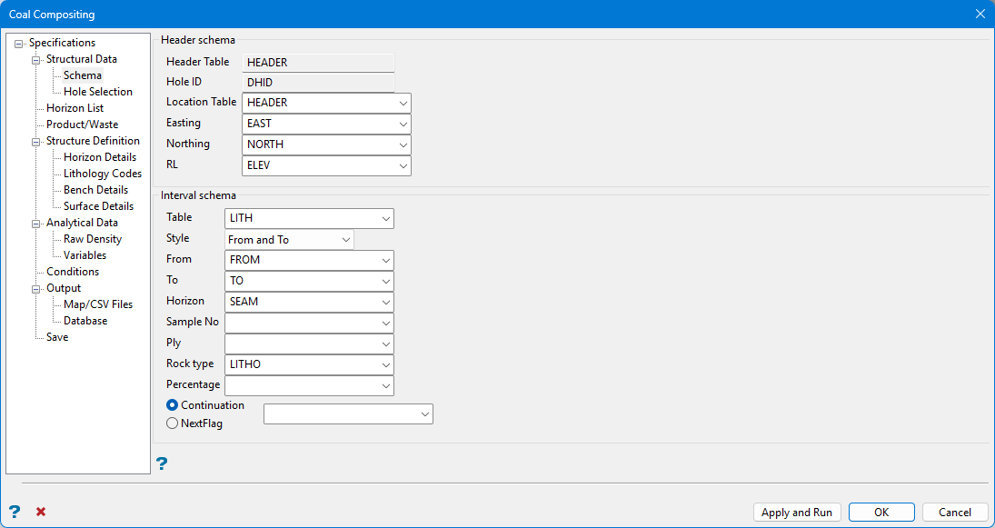
Use caution when overriding fields associated with database synonyms in panels.
Header schema
Header Table is populated with the table which is defined by the hole ID and location synonym sets.
Hole ID calls the field set as the Primary Key in the database.
By default, the Location Table is set to the table which is defined by the hole ID and location synonym sets. Change the Location Table, and its associated fields, with drop-down menu selections.
Missing entries here can affect other parts of the specification, for example if you do not define a sample number field, then you cannot use sample number as a lookup method into the analytical data.
Easting, Northing and RL fields are tied to the selected Location Table. If the Location Table changes, redefine Easting, Northing, and RL so compositing functions properly.
Interval schema
The Table defined by the geology synonym set is used to initially populate Interval schema fields. Make alterations to fields with drop-down selections.
For this dataset, use the logged depths in the LITH table to define the intervals and then match these intervals to depths in the QUAL table selected later in Analytical Data.
It is possible to use depth information within a QUAL table directly if required.
From, To, Horizon, Sample No, Ply, Rock type and Percentage fields are tied to the Table selected. If the Table changes, redefine From, To, Horizon, Sample No, Ply, Rock type and Percentage so compositing functions properly.
Style
There are three different ways to define depth in a database. Choose the appropriate definition Style from the drop-down list.
-
From only
-
To only
-
From and To
Important If From only or To only is selected, it is important that the data in the specified Table is logged continuously without missing intervals. Non-logged intervals may cause erroneous results.
Horizon
Values in the selected Horizon field must match horizons defined in the horizon list.
Sample No / Ply
Sample numbers and Ply names further define From and To intervals.
If using two or more tables to source quality values, quality tables chosen in Analytical Data must have Sample No or Ply names which exactly match those fields in the selected Structural database. All names are case-sensitive.
Rock type
This further refines what is considered product and what is considered waste later in the compositing process. For information on how this field is used.
If there is a field in the Table specified which is associated with the rocktype synonym in the database design, Rock type will populate with the name of that field. If required, make another selection from the drop-down list.
Percentage, Continuation and Nextflag
Avoid repeated interval errors when a database has repeated intervals in the lithological table designed to define multiple interbedded rock types or to give additional description to an interval. Our example does not contain such information, but if it did, fields would automatically populate based on defined database synonyms.
Hole Selection
Drillholes can either be limited by name or by position. If none of the options in this section are selected, then all available drillholes will be used. Entries in the nominated drillhole selection files (.sel), as well as the drop-down lists, may contain wildcards (both * multiple and ? single character).
You can create a drillhole selection file by selecting drillholes of interest, then right-click and select Drillhole > Selection File from the context menu to enter a file name and save the .sel file for future use. This essentially creates a text file that contains a list of hole identifiers with the format shown below. You can also create a selection file manually using a text editor and saving the file with the .sel extension. Note that drillhole names in the selection file are case sensitive.
Drillhole selection file format:
DD00026
DD00035
DD00044
DD00053
DD00116
DD00143
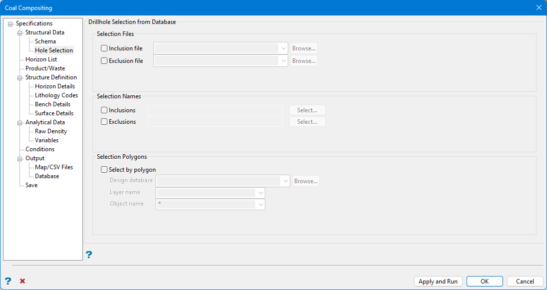
Selection Files
Use selection files (. sel) to include or exclude a large number of drillholes.
Selection Names
To include or exclude three or fewer drillholes, enter collar names directly in the Selection Names area. Entries are saved in the FixDHD specification file for use in later runs.
Drillhole names entered in the pane are case-sensitive.
Select by Polygon
Select by polygon spatially includes include drillhole collars which fall inside a defined polygon.
Design database
Specify the design database that contains the layer and polygon object. The drop-down list contains all design database files found in your current working directory. Click Browse to select a file from another location.
Layer name
Specify the name of the layer that contains the polygon object. The drop-down list will contain all layers found in the chosen design database.
Object name
Enter the name of the polygon object that will be used to limit the drillholes. Wildcards (both * multiple and ? single character) can be used.
Horizon List
Use Horizon List to define a horizon list, which can be used further down the panel when selecting horizons for compositing.
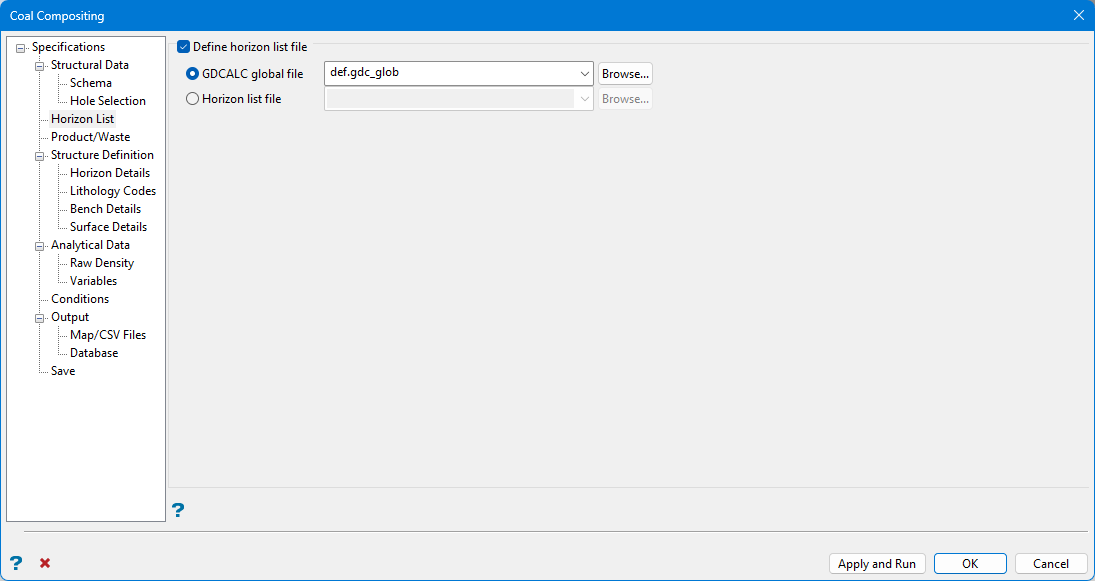
Define horizon list file
Select this checkbox to define a horizon list file to be composited.
GDCALC global file
Select this option to use the horizon list contained in an existing GDCALC global file (.gdc_glob). The drop-down list contains all .gdc_global files found in you current working directory. Click Browse to select a file from another location.
Horizon list file
Select this option to use the horizon list contained in an existing Horizon list file (.hzn).
In the situation where the deposit contains split horizons, one must consider how to treat qualities. There are a few strategies to consider:
Quality information for the parent seam and any child horizons is considered and modelled entirely separately. Grid masks are used when reserving to ensure that only the parent qualities are used for the extent of the parent, and child qualities for the extent of the child horizon.
The entire envelope of a split horizon is considered when compositing qualities. This means that the region from the top of the uppermost split to the base of the lowermost split is used across the extent of the parents and children. This involves compositing in partings between splits.
Only child horizons are composited. A weighting method is used where parent seams exist to artificially split them in into child quality values. If there is no breakdown of quality sampling within a parent horizon, then each child is given the full quality value of the parent seam.
The methodology in part c is combined with a Run of Mine (ROM) horizon compositing exercise to produce ROM grids. These grids combine and split on mining rules, not geological logging.
Product Waste
Use Product/Waste if you to use rock codes to determine product waste if you have setup a rock code field in the structural schema, and have setup the Lithology Codes section. If an interval matches the given lithology then it is defined to be product, if it does not match then it is defined to be waste.
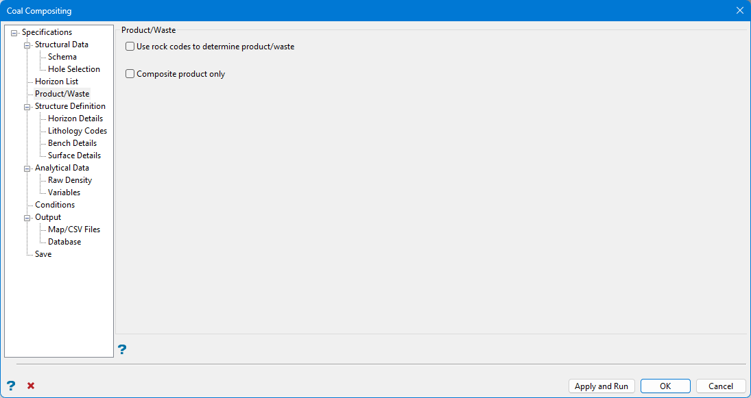
Select Use rock codes to determine product/waste to refine what is considered product and what is considered waste. Entries in the field in the database which is associated with the rocktype synonym are used. If a different field was selected as the Rock Type field in the Schema panel, the field chosen in the Schema panel will override the field associated with the rocktype synonym in the database.
-
This option is active after a Rock Type field is chosen in the Schema pane under Structural Data.
-
Definition of product and waste are configured in the Lithology Codes pane under Structure Definition.
Select Composite product only to only consider product in the resultant composites. The thickness of any waste is excluded.
Structure Definition
Use Structure Definition to define the top and bottom of the structure that will be composited for each hole. The various methods all produce a top and bottom downhole depth per hole.
The methods available for both the top and bottom are by horizon, bench level, surface model, or by a height (vertical distance between the top and bottom). This can be modified by offsetting both the top and bottom by a vertical distance, and also a minimum and maximum thickness can be applied to the structure when it is applicable.
You are also able to refine the structure by lithology codes (rock type) which means that a search is made from the top and bottom of the structure to find the first interval respectively that match the rock code definition, for example, the first coal interval.
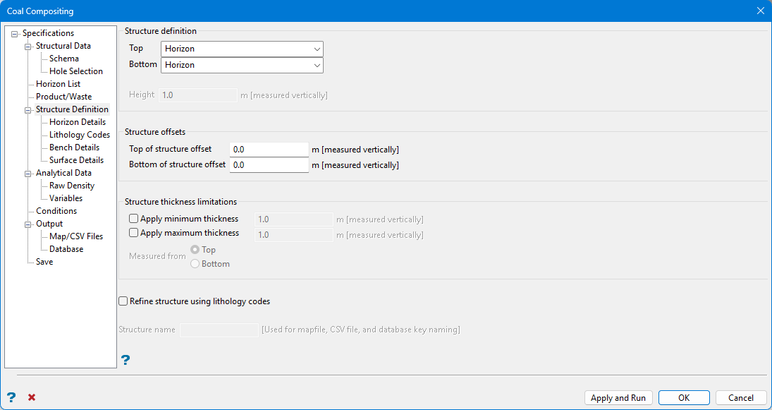
Structure definition
This section allows defines the top and bottom of the structure to composite for each drillhole. The various methods all produce a top and bottom downhole depth per drillhole.
Note: Options in the Horizon Details, Lithology Details, Bench Details, and Surface Details panes activate based upon selected Structure definition method(s).
Define Top or Bottom structures by:
-
Horizon
-
Bench Level
-
Surface Model
-
Vertical distance defined from the top or bottom
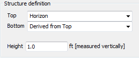
Top
These selections will control the top of the composite. The following options are available:
Horizon
The top of the composite coincides with the first interval of a given horizon.
Bench Level
The top of the composite coincides with a defined elevation. Levels are defined in the Bench Details pane.
Surface Model
The top of the composite coincides with the intersection of a defined surface. The surface is selected in the Surface Details pane.
Derived from Bottom
After selecting this option, enter a vertical Height.
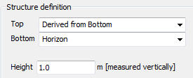
This option may be used in conjunction with any of the Bottom Structure definition options except Derived from Top. The result is an interval in each drillhole derived by relative thickness from a selected Horizon, Bench Level or Surface Model which defines the bottom of the composite.
Bottom
These selections will control the bottom of the composite. The following options are available:
Horizon
The bottom of the composite coincides with the last interval of a given composite.
Bench Level
The bottom of the composite coincides with a defined elevation. Levels are defined in the Bench Details pane.
Surface Model
The bottom of the composite coincides with the intersection of a defined surface. The surface is selected in the Surface Details pane.
Derived from Top
After selecting this option, enter a vertical Height.
This option may be used in conjunction with any of the Top Structure definition options except Derived from Bottom. The result is an interval in each drillhole derived by relative thickness from a selected Horizon, Bench Level or Surface Model which defines the top of the composite.
If a Bench Level or Surface Model intercepts the drillhole outside the ultimate drillhole depth, then the part of the hole that is beyond the drillhole depth is considered missing lithology. This may or may not cause an error depending on how data is handled when defining Variables under the Analytical Data folder.
Structure offsets
E nter Structure offsets to offset the top and bottom definition by a vertical distance. Use these options to quickly simulate a simple loss or dilution. For example, without adding intervals to the input database, use Structure offsets to create grids which are a set distance, such as 10 centimetres, from roof and floor grids.
Top of structure offset
Enter the vertical distance to offset from the top of the structure.
Bottom of structure offset
Enter the vertical distance to offset from the bottom of the structure.
Structure thickness limitations
Optional Structure thickness limitations can force a minimum and/or maximum thickness if applicable.
Check Apply minimum thickness to define a minimum thickness requirement. Composited structures that are less than the specified thickness are increased in size to the minimum thickness value.
Check Apply maximum thickness to define a maximum thickness requirement. Composited structures that are greater than the specified thickness are decreased in size to the maximum thickness value.
Select whether the entered minimum or maximum values will be Measured from the Top or the Bottom of the structure.
Refine structure using lithology codes
Lithology codes can further refine the structure using the field in the database which was assigned the Rock Type synonym. If a different field was selected as the Rock Type field in the Schema panel, the field chosen in the Schema panel will override the field associated with the rocktype synonym in the database.
A search is made from the top and bottom of the structure to find the first interval that matches the lithology code definition. For example, the first coal interval.
Note: If Derived from Bottom or Derived from Top is a Structure definition choice, this option is not available.
Structure Name
Enter a Structure name identifier for the resulting output data.
-
Structure name is active if Horizon is not a Structure definition choice.
-
Generated mapfiles will not have a standard naming convention.
Horizon Details
Use Horizon Details to define the structure by selecting one or more horizons or a horizon range. It also performs a simple horizon validation of the structure.
This option is only available if you select Horizon for either the top or bottom structure definition on the Structure Definition panel.
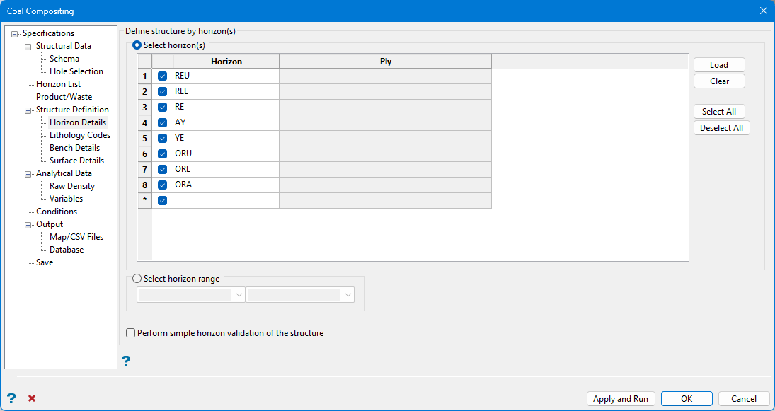
Define structure by horizon(s)
Select horizon(s)
Click Load to populate the panel with Horizons defined in the nominated horizon list file.
Select the box before each listed horizon to activate or deactivate a Horizon.
If the database contains Ply field with an associated Ply synonym, the Ply column in the table activates. Horizon matching is performed based upon a concatenated name derived from the Horizon and Ply data.
Select horizon range
Instead of listing each horizon of interest in the Select horizon(s) table, it is possible to define a range of horizons. The range is defined as the top of the first horizon selected in the drop-down menu on the left to the bottom of the horizon selected from the drop-down menu on the right.
This method may potentially include substantial intervals of interburden or parting between horizons.
Perform simple horizon validation of the structure
Select this checkbox to perform a simple validation check to reject holes from the composite if tests fail. Failures occur if ply values are not in the ply list for that horizon or in the correct order downhole, or horizon names different to the horizon being composited appear in the horizon list, or if a range of horizons is being used and the downhole order of these is incorrect based on the horizon list.
Lithology Codes
The use of lithology codes is optional. If required, provide allowable rock types to define which intervals are waste and which intervals are product based on both the logged horizon name and a rock type. Defined rock types correspond to entries in the field in the database associated with the rock type synonym.
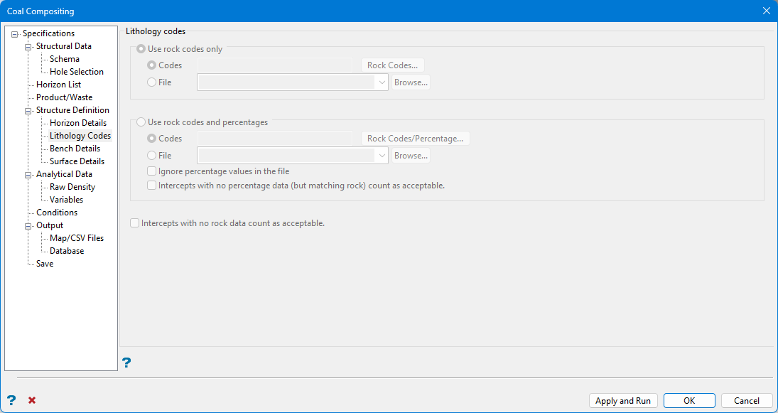
Lithology codes
Use rock codes only
Rock codes further define which portions of a horizon are considered product. Define a Rock type field on the Drillhole Scheme pane to use this option. Next, define Rock codes on the Lithology pane in one of two ways:
-
Enter Codes directly into the pane.
-
Select an existing text File.
Note: In both cases, separate rock codes with commas or spaces. Entries are case-sensitive. An example may be ST, CO or ST CO.
Use rock codes and percentages
Rock codes and percentages further define which portions of a horizon are considered product.
As an example, assume CO is a defined rock code with a percentage of 50. If a continued interval is defined as 70% Sandstone ( SS ) and 30% Coal ( CO ), the interval would be considered waste.
Define fields which contain Rock types, Continuation codes, and Percentages on the Drillhole Scheme pane. Next, define Rock codes and percentages on the Lithology pane in one of two ways:
-
Enter Codes directly into the pane.
-
Select an existing text File.
Note: In both cases, separate rock codes and percentages with commas. Separate rock code/percentage combinations with commas or spaces. Entries are case-sensitive. An example may be CO, 50 CL, 20 or CO, 50, CL, 20.
Ignore percentage values in the file
Select this box to ignore the percentage values contained in the selected text file.
Intercepts with no percentage data (but matching rock) count as acceptable
This is selectable when defining Rock codes and percentages earlier in the Lithology pane. The option includes database intervals where rock type matches defined codes, but no percentage data is included.
The same file may be used both for codes alone and for codes and percentages. Percentage values will be ignored if they are present when used for codes alone. Missing percentage values will be treated as 100% when used for codes and percentages. In all cases, the rock codes provided may contain wildcards. For example, C* will match all occurrences of CO, CD, or CL on an intercept record).
Intercepts with no rock data count as acceptable
Select this to include database intervals where the rock type has not been logged as part of the product.
Bench Details
Bench definition options are available if Bench Level was selected as a Structure definition.
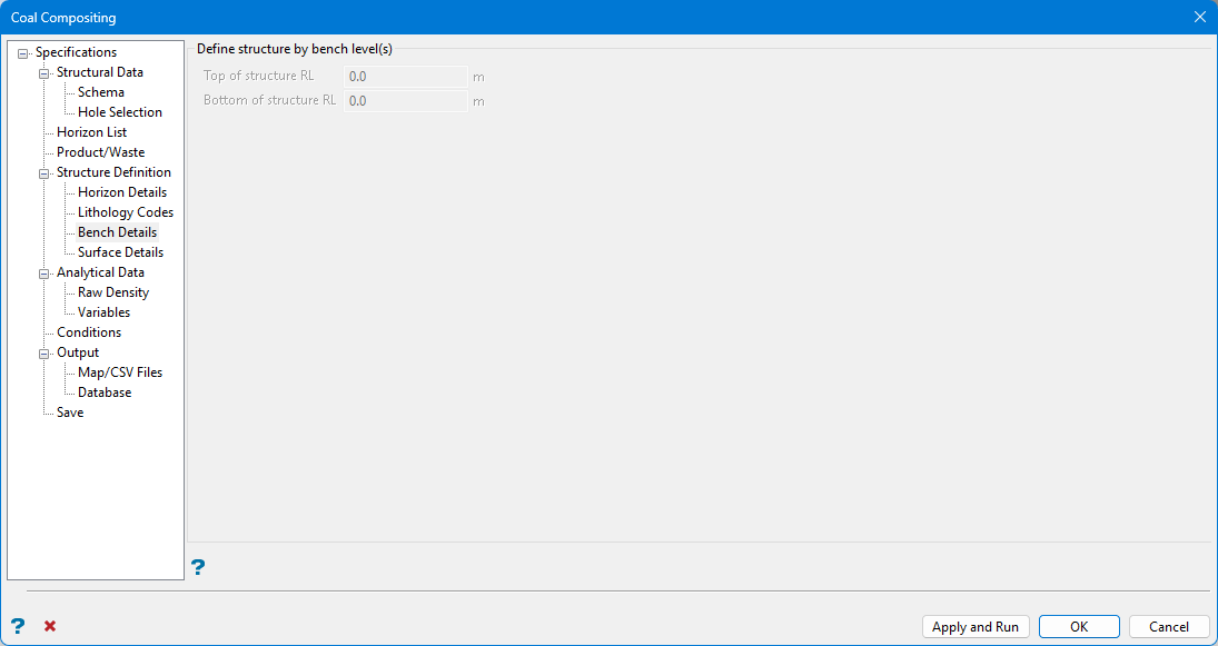
Note: Displayed length units reflect units defined in the DG1.
Enter elevations which define the lower bench and upper bench.
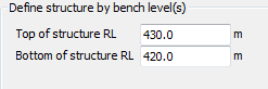
Using the example in the figure above, compositing would find all quality information in the drillholes falling between elevations of 420 and 430 and output a single weighted composite value to a mapfile named defbench420.map.
The result of this method is a composite for a single bench.
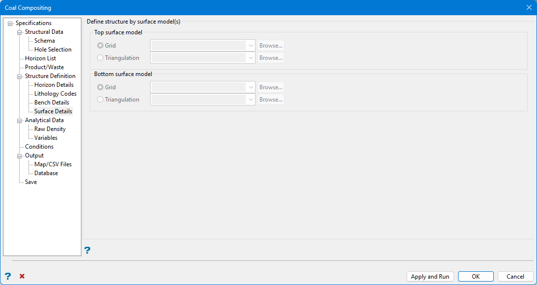
Surface Details
Note: Surface Details options are active when Surface Model is selected in the Structure Definition pane.
Surface definition can derive from any combination of triangulation or grid surfaces. Solid triangulations are not acceptable selections.
As grid models do not exactly honour data points, one method is to use a triangulation surface created from appropriate mapfile points. This procedure guarantees a perfect match at the drillhole intersections.
Define structure by surface model(s)
Select the surfaces that define the uppermost and lowermost extents of the composite. Click Browse to select surfaces from a location other than the current work area.
Define the output Structure name identifier on the Structure Definition pane.
Defining structures is useful when benches are not defined at a stagnant elevation. This is the case when benches are designed to allow for drainage. If using structures to composite across a family of horizon splits, select the uppermost, unmasked split roof and the lowermost, unmasked split floor. These surfaces are usually the roof and floor of the parent horizon.
Analytical Data
Use Analytical Data to define any analytical sources that you will be using, for example any database that contains a field that you want to composite. If you have a separate database that contains the raw density, and density is needed for the composites, then the database must be defined in this section of the panel. If your analytical data is in the same database as the structural data, you will also need to specify it here.
Options in Analytical Data define where and how TO and FROM values in the database chosen in Structural Data are matched to the database selected here.
This data may come from:
-
The same table defined in the Structural Data pane.
-
A different table within the same database defined in the Structural Data pane.
-
A completely different database.
Select the database and define the schema. The header table and hole ID field are displayed but cannot be edited.
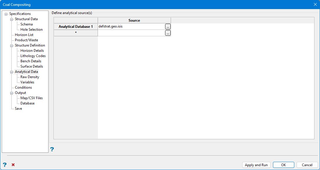
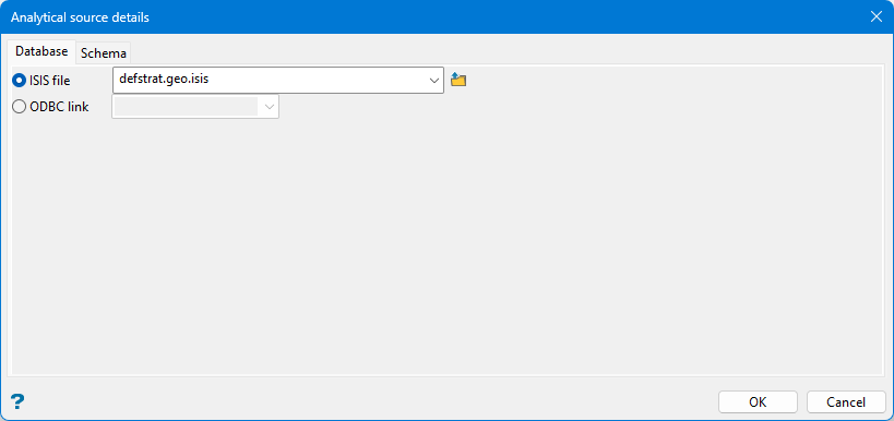
Define analytical source(s)
Click  to define each database. Select either an ISIS File or ODBC Link style database. It is possible to define more than one database.
Note: Some commonality between database fields is required to allow options to match correctly. Typically, this is accomplished through depths or sample numbers.
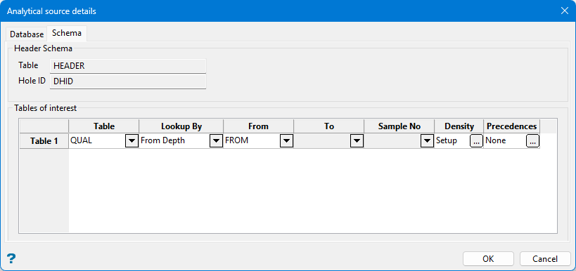
Header Schema
The table and hole ID information are displayed here.
Table of interest
Table
Select from the drop-down list the table that contains a field that you want to composite.
Lookup By
Select from the drop-down list the lookup value to be used to match the interval in the structural data to the interval in the analytical data. This can be by depths (if the depths in the analytical data are trustworthy), or by sample number (if you have defined a sample number field in the structural schema).
If you have correct depths in the analytical data, then looking up by depth can be used. If you have sample numbers in the analytical data, and you have a Sample No field setup in the structural schema, then you can lookup by sample number.
Note: The Sample No drop-down list will be unavailable unless there is a Sample No field in the structural schema.
From/To/Sample No
Select from these drop-down lists depending on the lookup method being used.
Density
Click to enter the density values if you are compositing by mass or mass-yield and require density for your weighting calculations. The following panel is then displayed.
You can setup a density field per table, and specify a default value if the density value is empty for any given interval. You can also setup a raw density source for the entire compositing run. The priority is set to:
- Value in the field
- Default value for that table (product and waste)
- Raw density
- Default raw density (product or waste)
Table density values
Define density field
Select this checkbox to composite a density field in the drilling database.
Density field
Select from the drop-down list the density field to use.
Null Value
Enter a value to be used as the null value. Values matching this in the data source will be ignored. Leaving this field blank, or entering a value of 0.0, will disable null checking.
Define density defaults
Select this checkbox to define density default values. A default value is used if the density value is empty for any given interval.
Product Density Value
Enter the default density associated with the Product Code.
Waste Density Value
Enter the density value associated with the Waste Code.
Note: If you make any changes to your analytical source selections, and there are some compositing variables using a database/table combination that is no longer defined in the analytical sources, then Vulcan will prompt you as to whether or not you want to clear the variables. If you choose to clear the variables, then any variables that do not match the analytical source information will be removed.
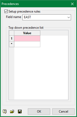
Precedences
Click to define the preferred order of usage in the situation where a text type field indicates (for example) differing analysis regimes.
Raw Density
Use Raw Density select the raw density field if it is required for compositing but is located in a different source. The selection is limited to databases that have been set up as an analytical source via the Analytical Source Details section, so as to allow a lookup of the density value for a given interval.
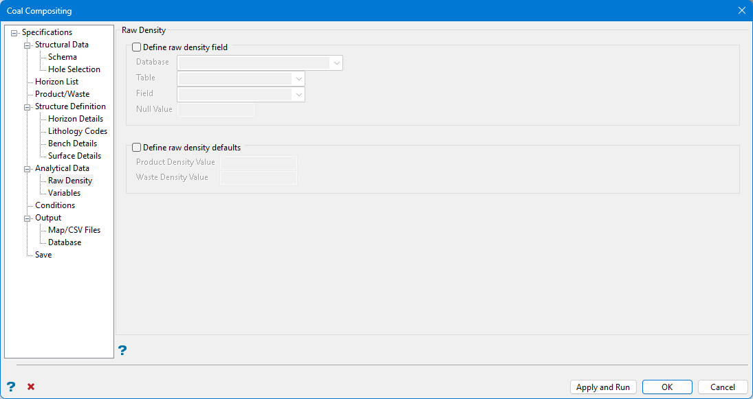
Define raw density field
Select this box to define the raw density field.
Database
Select from the drop-down list the database which contains the raw density.
Table
Select from the drop-down list the table that contains the raw density.
Field
Select from the drop-down list the raw density field.
Null Value
Enter a value to be used as the null value. Values matching this in the data source will be ignored. Leaving this field blank, or entering a value of '0.0', will disable null checking.
Define raw density defaults
Select this box to define raw density default values. A default value is used if the density value is empty for any given interval.
Product Density Value
Enter the default density associated with the Product Code.
Waste Density Value
Enter the density value associated with the Waste Code.
Variables
Use Variables to setup the variables that you want to composite.
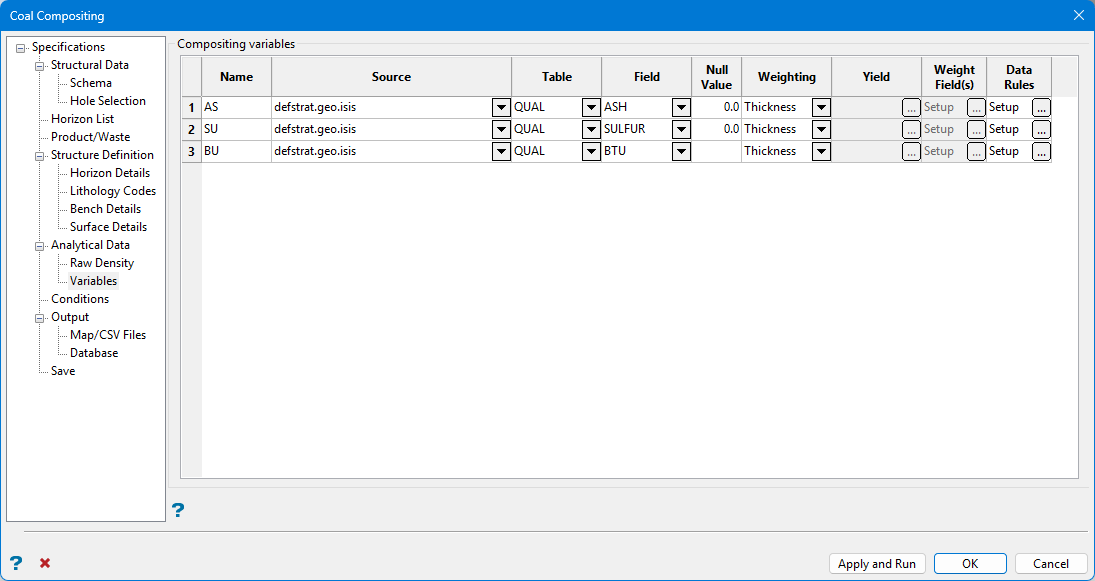
Composite variables
Name
Enter the name that the variable will have in the output. The variable name must have six or less unique, uppercase characters containing no spaces.
Source
Select from the drop-down list an analytical source that has been set up. This is selected from the list of analytical sources that have been set up.
Table
Select from the drop-down list a table to be composited. This is selected from the tables that have been setup for the selected analytical source.
Field
Select from the drop-down list the field that you want to composite. This field is selected from the numeric fields in the selected table.
Null Value
Enter a value to be used as the null value. Values matching this in the data source will be ignored. Leaving this field blank, or entering a value of '0.0', will disable null checking.
Weighting
Select from the drop-down list the weighting value to use. If there is a density value setup, then various mass options will be available for selection.
Yield
Click  to use the yield for weighting. Once selected, the Yield Details panel displays.
Select from the drop-down list the yield field and specify a null value. The Yield column is only applicable when the 'Yield' or 'Mass/Yield' or 'Mass/Yield' entries have been selected from the Weighting column of the Coal Compositing interface.
Weight Field(s)
Click to weight a composite by a selection of variables on the same table. Once selected, the Weighting Fields panel displays.
Select the fields to apply as weighting variables. You will need to select the variable name and, if desired, specify null and default values. The default value will be used if the field value is not found for a given record.
You can also specify whether the weighting should include the thickness, and if density has been defined, whether you want the weighting to be based on mass instead, or alternatively not weighted by thickness or mass. The Weight with mass option will only appear when density is defined somewhere in the specification.
Default values are always applied if the true field value is not available for any reason, for example the lookup into the analytical table found nothing, they have a null value or empty value in the field. Missing densities and weightings, which are replaced by default values, are not treated as missing data for the percentage cutoff section of the missing data rules.
The Weight Field(s) column is only applicable when the 'Other' entry have been selected from the Weighting column of the Coal Compositing interface.
Data Rules
Click to specify the rules that need to be applied to missing data that the composite cannot calculate. Once selected, the Missing Data Rules panel displays.
The Missing Data Rules panel is used to select rules to follow if data is missing for intervals of product, intervals of waste, and gaps in lithology. The following options can be select from the drop-down list:
- Ignore Interval
Specifies that the interval is not used for the composite. - Apply default value
Specifies that missing data will use the value that has been entered through the Default Value field, unless if requiring density and/or yield, in which case an error will still be flagged. - Flag an error
Specifies that missing data for this variable displays as an error and not composited.
Select the but flag an error if more than checkbox to display an error in the log when missing data is above the specified thickness percentage.
Conditions
Conditions allow for use of data that would fail basic overlapping interval validation tests. A logical condition isolates all valid rows of data, and uses these rows when compositing.
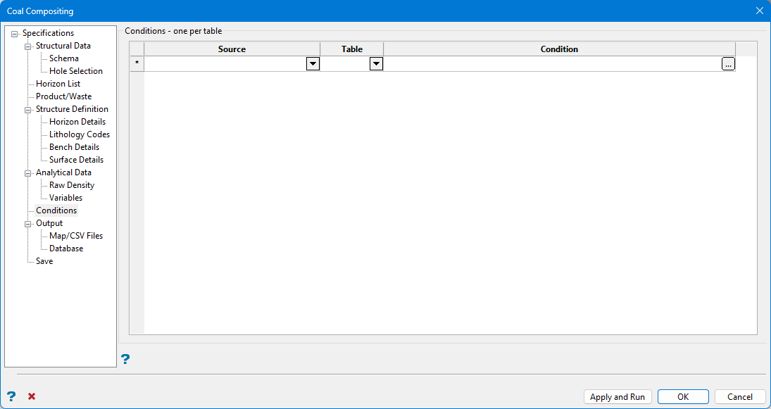
Specify the data source and table. Click in the Condition column to enter a condition. Once selected, the Conditional Expressions panel displays.
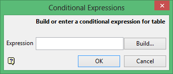
Enter the condition. Click the Build button to construct the condition using Vulcan's SQL Expression Builder tool. Once selected, the Build Expression panel displays.
The Build Expression panel consists of the following key areas:
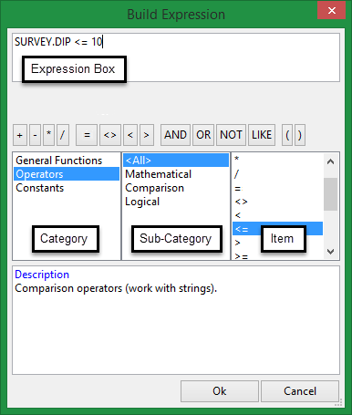
- Expression Box
This section is used to construct the SQL expression. Text values, such as layer names and object descriptions, must be enclosed within single quotes, for exampleLAYER_NAME LIKE 'LINE_2'. - Operator Button Bank
This section contains a collection of common operators that can be used to construct valid SQL expressions.Button Description Notes = Equal to <> Not equal to < Less than Adding a '=' symbol after the '<' will allow you to match conditions that are less than or equal to. > Greater than Adding a '=' symbol after the '>' will allow you to match conditions that are greater than or equal to. AND Joins two or more conditions and displays the data that satisfies ALL specified conditions OR Joins two or more conditions and displays the data that satisfies ANY of the specified conditions NOT Not like a specified pattern An asterisk ( * ) can be used to match any possible characters that might appear before or after the characters specified, while the underscore (_) is used to match any single character that may appear before or after the characters specified. LIKE Like a specified pattern An asterisk ( * ) can be used to match any possible characters that might appear before or after the characters specified, while the underscore (_) is used to match any single character that may appear before or after the characters specified. >= Greater than or equal to <= Less than or equal to ( ) Should be used to enclose any field names that contain spaces or to enclose identifiers that match SQL reserved words - Category, Sub-category and Item columns
This section contains a list of predefined SQL functions. The functions displayed through this section are dependant upon the Vulcan option that is current being used.
SQL conditions can be entered directly into the Expression Box. However, if you are not familiar with SQL, we recommend using the available Operator Button Bank, Category, Sub-category and Item columns. Conditions will be coloured red if the syntax is incorrect.
Output
Use Output to output composited variables to a standard mapfile, CSV file, or composite database.
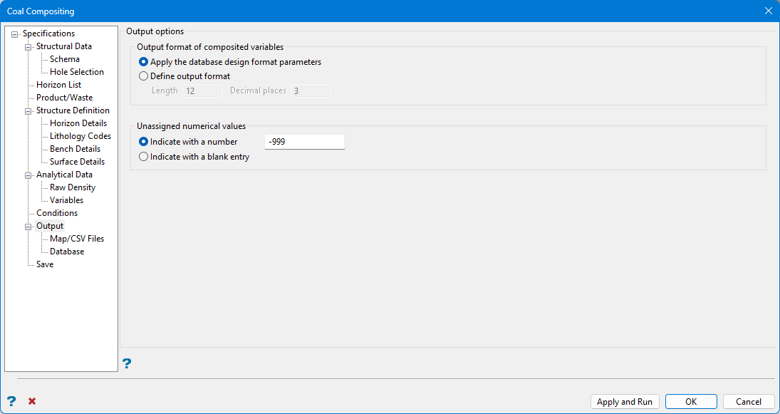
Output format of composited variables
Select the output format for composited variables; this can be either the same format as the design from the analytical database, or a fixed setting for all variables. Integer fields will ignore the decimal places.
Unassigned numerical values
These options allow you to assign a value for variable if it does not composite but other variables do (for a given hole). Select whether to set the value in the mapfile or CSV file to the unassigned value or just leave the field empty. Be careful when using the null value option as the format of the field may truncate the value, for example you can’t write -999 in a field of length 3.
Map/CSV Files
Use Map/CSV Files to define how to output composited variables to a standard mapfile or CSV file.
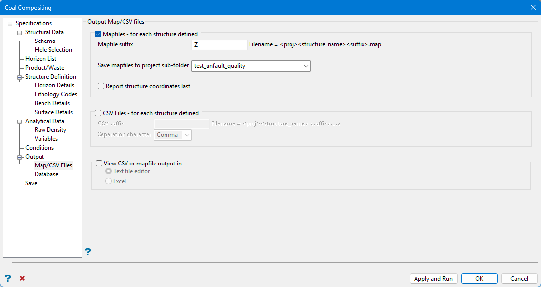
Mapfiles for each structure defined
Enable Mapfiles – for each structure defined to generate traditional mapfile output.
Enter a Mapfile suffix, if required.
Note: Although it is possible to enter multiple characters for the suffix, the resulting format is not compatible with older Grid Calc options.
If required, the mapfiles can save to a folder in the current work area. Select the folder from the Save mapfiles to project sub-folder drop-down list.
Note: Mapfiles saved to a folder cannot be accessed by older Grid Calc menu options.
Enable Report structure coordinates last to move the x,y,z coordinate columns farthest to the right in the output text mapfile. This is done mainly for readability in the mapfile. By putting the less important information out of the way, you can open up the mapfile in a text editor and easily see the more important values such as coal quality values or seam thicknesses, rather than having to scroll to the right.
CSV Files for each structure defined
Check CSV Files – for each structure defined to generate CSV files. It is possible reload CSV files to fixed drillhole style databases.
Note: While useful for viewing information, CSV files cannot be used to quickly populate horizon variables when constructing quality grids.
View CSV or mapfile output in
Check this to select whether the generated CSV or mapfile will launch in a Text file editor or Excel.
Database
Use Database to define how to output composited variables to a composite database.
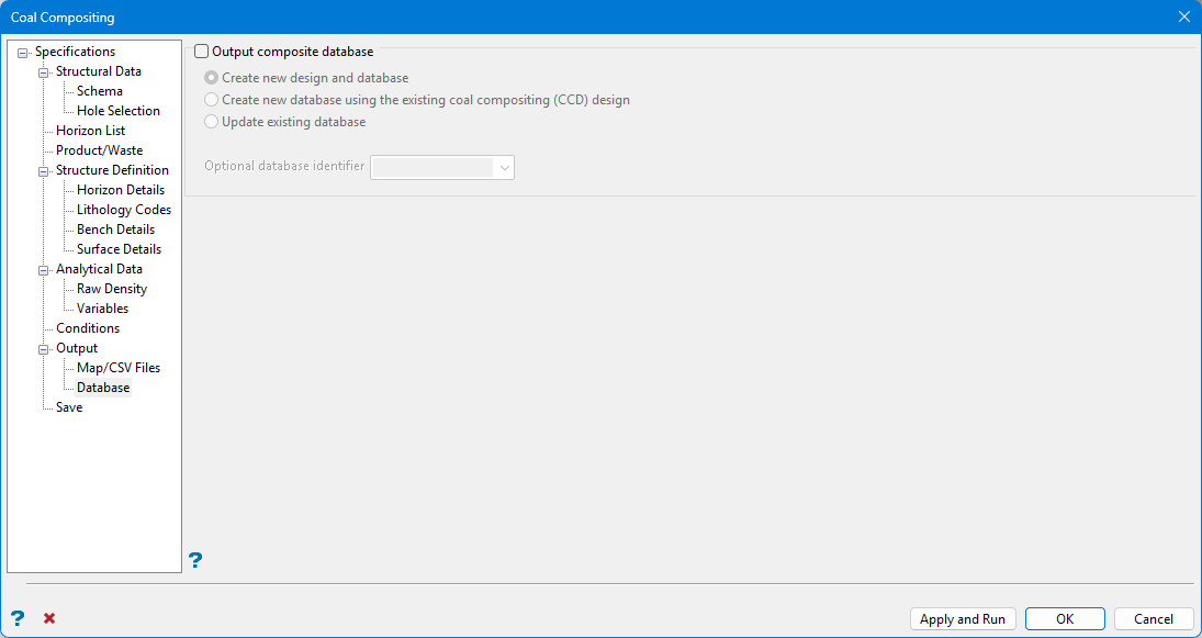
Output composite database
Check this option to generate output data to an Isis mapbase. Mapbases contain the same information as mapfiles, but in an Isis database format. The advantages of mapbases include:
-
A single mapbase replaces several individual mapfiles,
-
Mapbases are edited in Vulcan whereas mapfiles are accessible in any text editor. Therefore, mapbases provide better security.
-
It is possible to store data at an external source and access the data via an ODBC link.
-
Access to Isis field calculation and validation tools is available.
Save
Use Save to save any changes to the specification file and run the compositing.
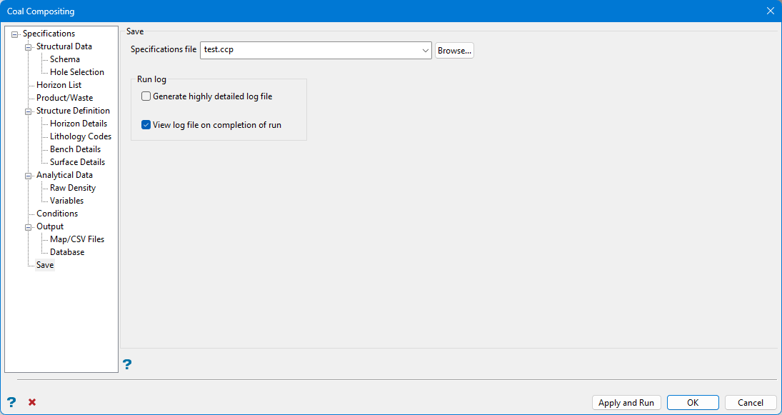
Specifications file
The Coal Compositing specification file saves with a <.ccp > extension. Click Browse to save the specification file to a location outside the current work area.
Click Apply and Run to save the specification and create the composited data. After compositing runs, a log information file automatically opens so any errors may be addressed.
Click Yes on the Model Qualities dialog box to create grids from data generated during compositing. This automatically launches Grid Calc > Create Multiple Surfaces.
Run log
Generate highly detailed log file
Select this checkbox to create a log file detailing which intervals were composited in each drillhole.
View log on completion of run
Select this checkbox to open the generated log file automatically on completion.
