Model to CSV
Use the Model to CSV option to export block values to a nominated CSV file. The resulting CSV file can be edited through software packages that recognise the CSV format, such as Microsoft Excel and Microsoft Access.
The format of the CSV file is:
|
Line 1 |
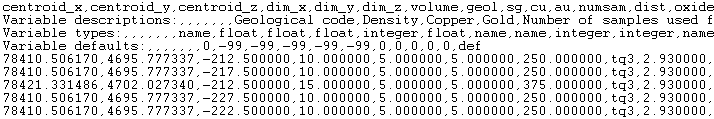
This line contains the field names of the data in the CSV file. These names consist of seven standard field names (X, Y and Z coordinates of the block centre, X, Y and Z lengths of the block and block volume), and the variable names (there is no limit to the number of variables). |
|
Lines 2, 3, 4 |
These lines contain information about the variable fields. Line 2 contains the variable description, line 3 the type and line 4 the default value. No data is contained in the first seven fields. The first field of each line does, however, contain the name. For example, field 1 of line 2 contains variable description. |
|
Lines 5 – end |
These lines contain the block data (one line per block). The block centroids are in real world coordinates. |
|
|
|
Figure 1: Figure 1 - Extract from a CSV file |
Tip: You can also use the external program BTOCSV to export a block model.
Note: Unlike the File > Export > Export to ASCII option, the Model to CSV option will export text field data as text. Vertical corner offsets, if they exist in the block model, will also be exported to the nominated output file.
Export a model to CSV as follows:
-
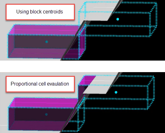
On the Block menu, point to Transfer, and then click Model to CSV... to display the Block Model to CSV File Transfer panel.
-
Enter or select the Block model name from the current working directory. Alternatively, Click Browse... to locate a block model to load from a different directory.
-
By default, the resulting CSV file will be stored in the same directory as the nominated block model and inherit the name of the block model file. Enter or select an alternative CSV output file name if required (all output files in the current working directory appear in the list). Alternatively, click Browse... to select a different directory.
Example: If your block model file is named demomodel.bmf, then the resulting file will be named
demomodel1.csv. -
(Optional) Select Export block IDs to export the built-in system block IDs to the output file.
-
Under Block Selection, choose between the following options:
-
All blocks to export all blocks to the CSV. Go to step 7.
-
Specific blocks to specify which blocks to export. Set the remaining options as follows:
-
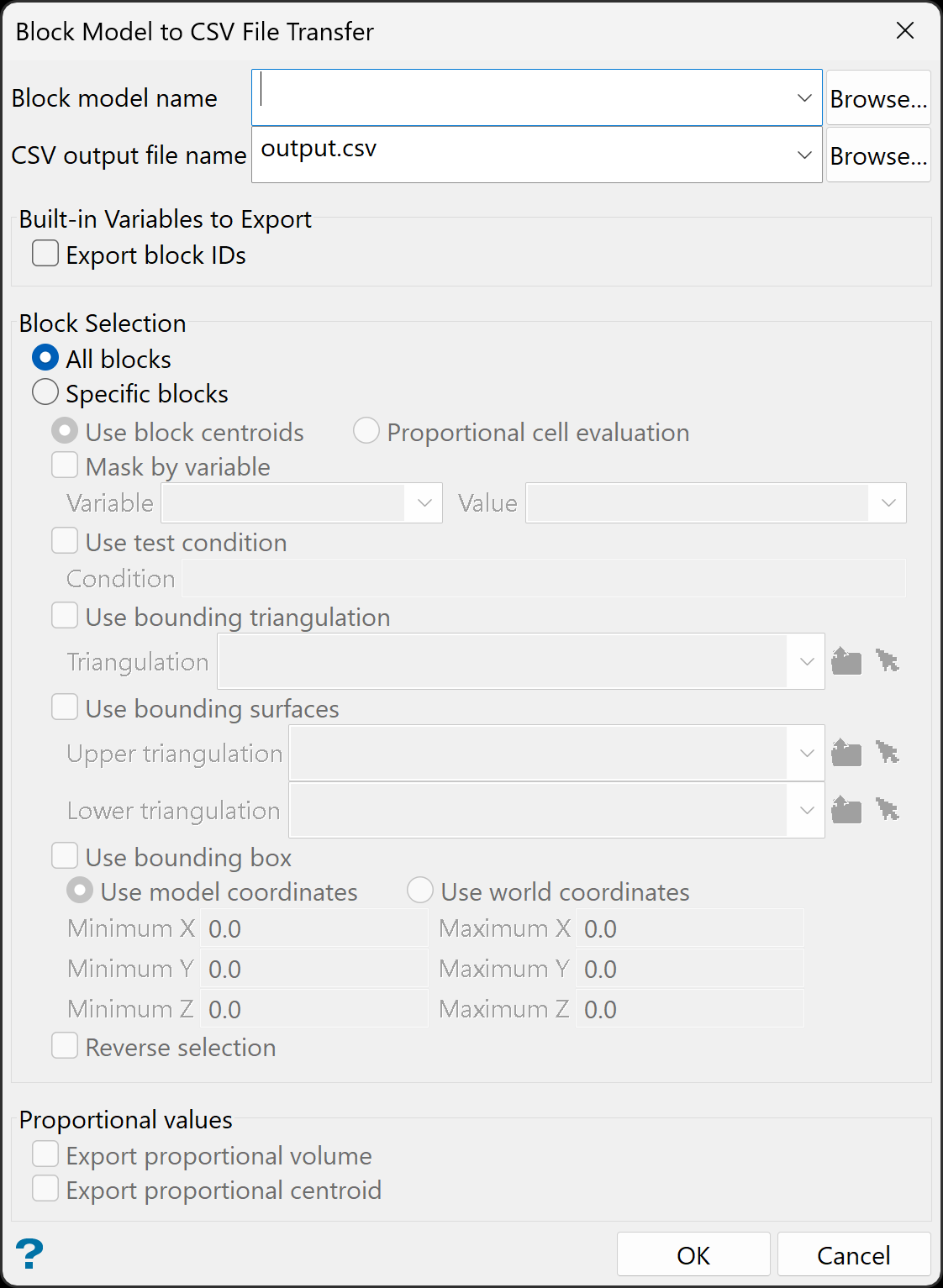
Decide whether you want to use the entire block in the calculations or only the portion that is within the regional boundaries. By default, the evaluation method is set to Proportional cell evaluation; however, you can select between Proportional cell evaluation and Use block centroids. This is especially important when using options such as Bounding triangulation, Bounding box, Section thickness, or Bounding surfaces.
-
Mask by variable
Select the Mask by variable checkbox to restrict the blocks by a block model variable. You will need to select the variable and value to mask by from the Variable and Value drop-down lists.
Example: To restrict blocks to those where Material equals Ore, select Material as the variable and
Oreas the value. The block model variable may be numeric, such as the grade variable Au or character, such as Geology variables. -
Use test condition
Select the Use test condition checkbox to use a further constraint upon a numeric block model variable and enter the condition in the Condition field. The maximum size of the condition is 132 alphanumeric characters.
Refer to the appendix, Operators and Functions, for a full list of available operators and functions.
Example: To select only blocks that have an iron value greater than 10.0, you would select the Use condition checkbox and enter
Fe GT 10.0in the Conditions field. -
Use bounding triangulation
Select the Use bounding triangulation checkbox to restrict the blocks by a triangulation. Select the bounding triangulation to use from the Triangulation drop-down list, or click Browse... to select a triangulation from a location other than your working directory.
Note: This option is not applicable to open or 2D triangulations.
- Use bounding surfaces
Select the Use bounding surfaces checkbox to restrict the blocks by bounding surfaces. Select triangulations from the Upper triangulation and Lower triangulation drop-down lists, or click Browse... to select triangulations from a location other than your working directory.
-
Use bounding box
Select the Use bounding box checkbox to restrict the blocks by a box. Choose either Use model coordinates or Use world coordinates, then enter the minimum and maximum X, Y, and Z coordinates as opposite vertices of the bounding box.
Note: If the block model origin is set at 0,0,0, then select Use world coordinates for the minimum and maximum X, Y, and Z coordinates. If the block model origin is set at real world coordinates, then enter coordinates for the bounding box that are offset a certain distance from the origin. The distance of offset will be determined by the dimensions of your bounding box. It will be the distance to the minimum and the distance to the maximum X, Y and Z from the origin of the block model.
-
Reverse selection
Select Reverse selection if you want to exclude the selected blocks within the slice. If this option is not selected, the entire block is included within the slice by default.
-
-
-
(Optional) Under Proportional values, select from the following, as required.
-
Export proportional volume to export the proportional volume.
-
Export Proportional centroid to export the proportional centroid coordinates.
-
-
Click OK.
The progress of the exporting process displays in a shell window.
