Pit Topography
Use this option to generate an updated pit topography, enclosed solid, clipped surface, topography outline, and base outline for a previous topographic surface against a surface of a new pit design.
Instructions
Launch the Pit Topography tool. On the Open Pit menu, point to either Open Cut Design or Integrated Stratigraphic Planning, then click ![]() Pit Topography.
Pit Topography.
Note: You can also access this tool by clicking the ![]() (Pit Topography) button on the Open Cut Design toolbar.
(Pit Topography) button on the Open Cut Design toolbar.
-
Inputs section
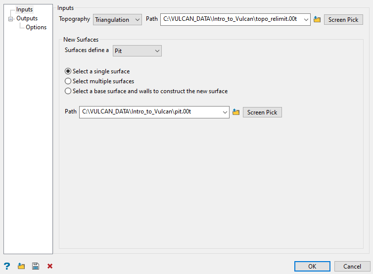
Complete the Inputs section as follows.
-
Select a Topography from the drop-down. Options are Triangulation, Grid model, or Fixed level.
If you selected Triangulation or Grid model, select one from the corresponding drop-down box, click the
 button and browse the local drive, or pick one manually from the view.
If you selected Fixed level, enter a value of the level at which to create the topography surface.
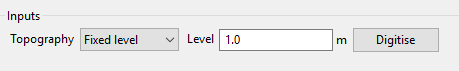
Tip: You can also click the Digitise button then pick a point on the screen. This will automatically calculate the value and fill the Level field.
-
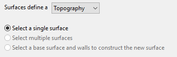
Define the New surfaces. Options are Pit, Dump, or Topography.
NoteIf you select a single surface, the new surface can be defined as pit, dump, or topography. If you select multiple surfaces or base surface and walls to construct a new surface, the new surface can be defined as only pit or dump.
-
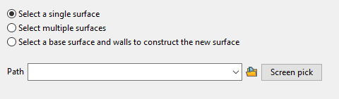
With the Select a single surface option, select a triangulation surface that represents pit, dump, or topography. Enter the path of the surface by browsing the local drive, or selecting one from the drop-down box, or picking manually from the screen.
-
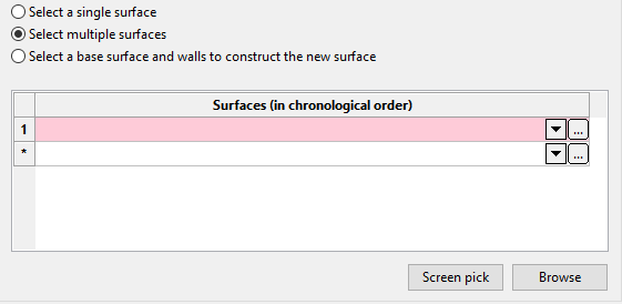
With the Select multiple surfaces option, select triangulation surfaces in a correct sequence or chronological order. You can select the triangulation surfaces by browsing the local drive, selecting one from the drop-down box, or picking manually from the screen. As each surface is processed in the selected order, the topography of one surface is updated and the resultant surface is used as the input for processing next surface until all surfaces are processed.
-
With the Select a base surface and walls to construct the new surface option, the selected surface will be used as the input for processing. The selected surface represents either a pit or a dump. The base surface can be selected as a triangulation, grid model, or fixed level. The walls can be either triangulations or design strings and the new surface can be saved with a different name and assigned a different colour.
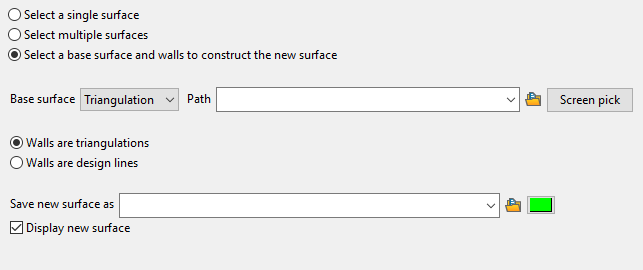
When constructing a pit shell, the base surface would be the pit floor and the walls would either be your projected strings or wall surfaces created previously. If multiple walls are selected, these should intersect such that a boolean operation will be able to create an enclosed region. If strings are selected, they will be triangulated using the standard surface triangulation method, so that the strings do not have any vertical projections. This will attempt to extend the Z range of the walls to enable intersection with the base surface and topography specified.
-
-
-
Outputs section
For each pair of input surfaces, several outputs can be created. You can select either or all of these outputs. Complete the Outputs section as detailed below.
Note: Outputs that are not selected will have red crosses on the tab header. If an output is selected the red cross will be replaced by a green tick, giving clear indication of the outputs that have been selected.
Enclosed Solid tab
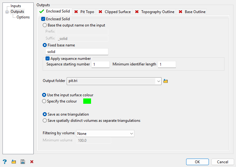
This creates the solid enclosed between the two surfaces. The enclosed solid is formed by the pushback of the new pit into the previous topography.
Follow these steps:
-
Check the Enclosed solid option to enable this output.
-
Select the naming option.
-
Base the output on the input. This method uses the name of the input solid and allows you to add a prefix and suffix to the name. This option is useful if you only have one input solid.
-
Fixed base name. This method allows you to enter a unique name.
-
-
Enable Apply sequence number to select a Sequence starting number that will be added to the name of the new solid.
When using multiple input surfaces and naming an output using a specified name rather than basing the output name on the input, an incremental numeric suffix beginning with
1will be appended to the name of each processed surface. This is to preserve unique output naming.Note: This option is only available if you select Multiple surfaces and Fixed base name.
-
Enter a Minimum identifier length. This will be used as a formatting place holder for the sequence number.
-
Select the folder in which to store the new solids by selecting the folder from the Output folder drop-down list, or by clicking the
button, then selecting the folder from the explorer panel or creating a new folder.Note: To create a new folder, click the New folder button and enter a name for the folder. Be sure to include the
*.triextension as part of the folder name or it will not be displayed as a triangulation folder in the Vulcan explorer pane. -
Define how you want to colour the output triangulation by selecting either Use the input surface colour, or choosing a custom colour after selecting Specify the colour.
-
Select either Save as one triangulation or Save spatially distinct volumes as separate triangulations.
When a boolean operation is performed on the two surfaces, this will frequently result in more than one distinct volume being generated. Often there will be one large volume and multiple smaller intersection volumes. Optionally, the you can save all or some of these separate volumes as one triangulation, or as separate triangulations. If saved as separate triangulations, a numeric suffix will be added to the name.
-
Select an option from the Filtering by volume drop-down list. This can prevent small, usable solids from being created. You can filter the separate volumes based on a minimum volume, or choose to simply keep the largest volume.
Pit Topo tab
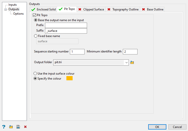
This creates the surface formed by applying the new design to the topography. For pit example, the photo surface is the new topography formed by mining the new pit design. For dump example, it is the new topography formed after the dump.
Note: This option is not available when the new surface defines a topography.
Follow these steps:
-
Check the Pit topo option to enable this output.
-
Select the naming option.
-
Base the output on the input - This method uses the name of the input solid and allows you to add a prefix and suffix to the name. This option is useful if you only have one input solid.
-
Fixed base name - This method allows you to enter a unique name.
-
-
Select a Sequence starting number that will be added to the name of the new solid.
When using multiple input surfaces and naming an output using a specified name rather than basing the output name on the input, an incremental numeric suffix beginning with
1will be appended to the name of each processed surface. This is to preserve unique output naming. -
Enter a Minimum identifier length. This will be used as a formatting place holder for the sequence number.
-
Select the folder in which to store the new solid by selecting the folder from the Output folder drop-down list, or by clicking the
button and selecting the folder from the Explorer panel or creating a new folder.Note: To create a new folder, click the New folder button and enter a name for the folder. Be sure to include the
*.triextension as part of the folder name or it will not be displayed as a triangulation folder in the Vulcan explorer pane. -
Define how you want to colour the output triangulation by selecting either Use the input surface colour, or choosing a custom colour after selecting Specify the colour.
Clipped Surface tab
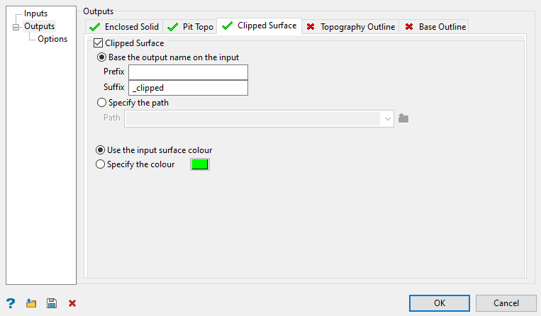
This creates a new surface based on clipping the new surface by the topography. It is equivalent to the enclosed solid without the closing topography component.
Note: This option is not available when the new surface defines a topography.
Follow these steps:
-
Check the Clipped Surface option to enable this output.
-
Select the naming option.
-
Base the output on the input - This method uses the name of the input solid and allows you to add a prefix and suffix to the name. This option is useful if you only have one input solid.
-
Fixed base name - This method allows you to enter a unique name.
-
-
Select a Sequence starting number that will be added to the name of the new solid.
When using multiple input surfaces and naming an output using a specified name rather than basing the output name on the input, an incremental numeric suffix beginning with
1will be appended to the name of each processed surface. This is to preserve unique output naming. -
Enter a Minimum identifier length. This will be used as a formatting place holder for the sequence number.
-
Select the folder in which to store the new solids by selecting the folder from the Output folder drop-down list, or by clicking the
button and selecting the folder from the Explorer panel or creating a new folder.Note: To create a new folder, click the New folder button and enter a name for the folder. Be sure to include the
*.triextension as part of the folder name or it will not be displayed as a triangulation folder in the Vulcan explorer pane. -
Define how you want to colour the output triangulation by selecting either Use the input surface colour, or choosing a custom colour after selecting Specify the colour.
Topography Outline tab
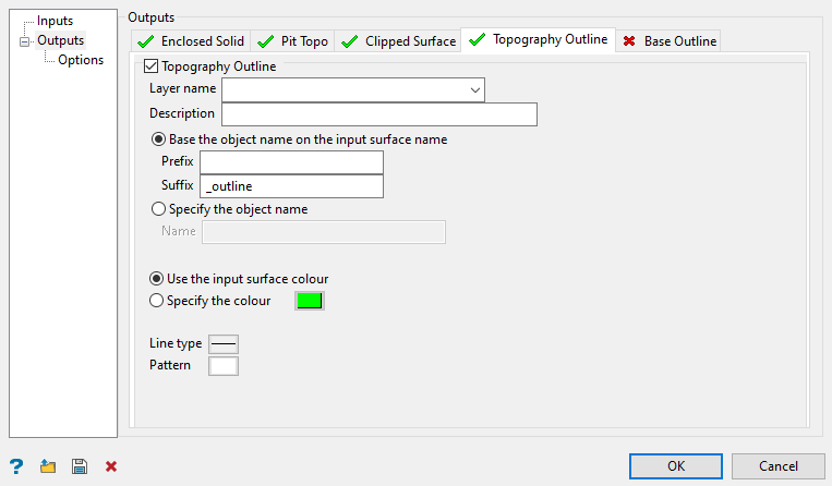
This creates the topography intersection polygon or polygons of the two surfaces. These are saved as design objects in the given layer.
Follow these steps:
-
Check the Topography Outline option to enable this output.
-
Select a layer from the Layer name drop-down list, or enter a name for a new layer.
-
Enter an optional Description to further describe the contents of this layer. The description can be up to 80 alphanumeric characters and may include spaces. If a description is not entered, then a default description will be used instead. If the chosen layer already has an assigned description, the description displays when the layer is selected. Existing layer descriptions can be overwritten.
-
Select the option to provide the layer with an object name. The naming of the object can be based on the input surface name with optional prefix and suffix, or a fixed name. This becomes important when using the Open Pit > Open Cut Design > Progress Maps option as it requires that the intersection polygon have an object name.
-
Base the output on the input - This method uses the name of the input solid and allows you to add a prefix and suffix to the name. This option is useful if you only have one input solid.
-
Fixed base name - This method allows you to enter a unique name.
-
-
Select a Sequence starting number that will be added to the name of each layer object.
When using multiple input surfaces and naming an output using a specified name rather than basing the output name on the input, an incremental numeric suffix beginning with 1 will be appended to the name of each processed surface. This is to preserve unique output naming.
-
Enter a Minimum identifier length. This will be used as a formatting place holder for the sequence number.
-
Select the folder in which to store the new solids by selecting the folder from the Output folder drop-down list, or by clicking the
button and selecting the folder from the Explorer panel or creating a new folder.Note: To create a new folder, click the New folder button and enter a name for the folder. Be sure to include the
*.triextension as part of the folder name or it will not be displayed as a triangulation folder in the Vulcan explorer pane. -
Define how you want to colour the output triangulation by selecting either Use the input surface colour, or choosing a custom colour after selecting Specify the colour.
-
Select a Line type and Pattern to apply to the layer.
Base Outline tab
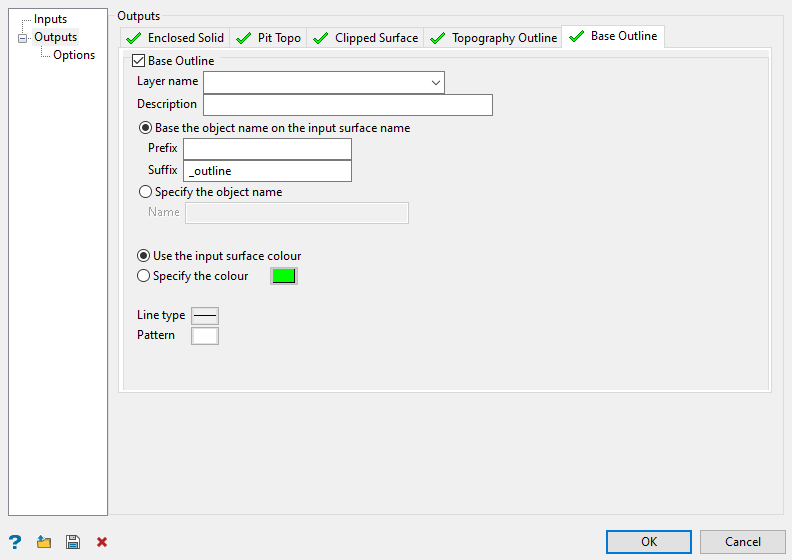
If you choose to create a new surface from a base and walls, the option to create the intersection polygon or polygons between the base and the walls will be available.
Follow these steps:
-
Check the Base Outline option to enable this output.
-
Select a layer from the Layer name drop-down list, or enter a name for a new layer.
-
Enter an optional Description to further describe the contents of this layer. The description can be up to 80 alphanumeric characters and may include spaces. If a description is not entered, then a default description will be used instead. If the chosen layer already has an assigned description, the description displays when the layer is selected. Existing layer descriptions can be overwritten.
-
Select the option to provide the layer with an object name. The naming of the object can be based on the input surface name with optional prefix and suffix, or a fixed name. This becomes important when using the Open Pit > Open Cut Design > Progress Maps option as it requires that the intersection polygon have an object name.
-
Base the output on the input - This method uses the name of the input solid and allows you to add a prefix and suffix to the name. This option is useful if you only have one input solid.
-
Fixed base name - This method allows you to enter a unique name.
-
-
Select a Sequence starting number that will be added to the name of each layer object.
When using multiple input surfaces and naming an output using a specified name rather than basing the output name on the input, an incremental numeric suffix beginning with 1 will be appended to the name of each processed surface. This is to preserve unique output naming.
-
Enter a Minimum identifier length. This will be used as a formatting place holder for the sequence number.
-
Select the folder in which to store the new solids by selecting the folder from the Output folder drop-down list, or by clicking the
button and selecting the folder from the Explorer panel or creating a new folder.Note: To create a new folder, click the New folder button and enter a name for the folder. Be sure to include the
*.triextension as part of the folder name or it will not be displayed as a triangulation folder in the Vulcan explorer pane. -
Define how you want to colour the output triangulation by selecting either Use the input surface colour, or choosing a custom colour after selecting Specify the colour.
-
Select a Line type and Pattern to apply to the layer.
-
-
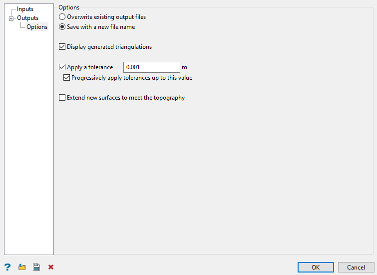
Options sub-section
Follow these steps:
-
Select how you want to save the resulting files.
-
If you select Overwrite existing output files, existing files of the same name will be silently overwritten.
-
If you select Save with a new file name, and the file name is already in use, it will try to form a unique name by append the name with
_iwhereiis an incrementing integer value starting at 1.
-
-
Select Display generated triangulations to load the triangulations onto the screen.
-
Select Apply a tolerance to use the given tolerance value when performing the boolean operations on the surfaces. The tolerance value is expected to be small, such as 0.001. In some cases, boolean can generate an invalid surface or solid when it cannot resolve close points or coincident regions. Adjusting the tolerance may resolve this.
-
Select Progressively apply tolerances up to this value to begin with a zero tolerance and apply a few smaller tolerances before finally applying the given tolerance, but stopping when a valid result is produced.
-
Select Extend new surfaces to meet the topography to vertically extend a pit surface upwards, or a dump surface downwards, to meet the topography. It will use a near vertical batter angle for the projection of the border strings of the pit or dump surface.
-
When you have finished configuring the settings, click OK to generate the required outputs.
You can also save all these settings in a specification (.spec) file and use them later. At the bottom-right of the panel, you can find options to save and load the specifications and clear the panel contents.
![]()
