Create Pit Design
This option allows you to create an open pit design or dump. It uses information from given block models to set slope and angle parameters by recognising different zones. Alternatively, you can set the parameters up as you go by defining them interactively. Design ramps with complete control over grade, width, and number of switchbacks. Save the results as a design file and triangulation.
The fundamental difference between the Automated Pit Designer and other open pit design tools is that instead of working bench-by-bench you define a specification which is automatically projected into a complete pit or dump design. In the pit designer, you will define the benches and the slope parameters first, then you will define the seed shapes and ramps. The pit designer will automatically recalculate the design as your parameters change, allowing you to make changes at the bottom of the pit, for example, and see immediately how that changes the pit higher up. This differs from the bench-by-bench design in which you would have to redraw the changed areas of the pit.
Design stages
Pit design is performed in stages. Expand below to see each design stage.
-
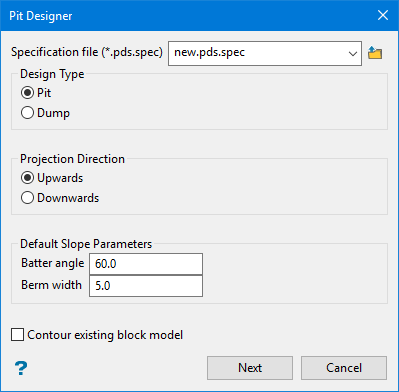
On the Open Pit menu, point to Automated Pit Designer, and then click Create Pit Design to display theCreate Design panel.
-
Select a Specification file (*.pds.spec) from the drop-down showing the current working directory, or enter a new name. Alternatively, click the
 button to browse to the required file’s location.
All the parameters you set up in the design process will be stored in this specification file. Once it is saved, you will be able to reopen your design work to make edits or continue where you left off. The specification file will be stored in your current working directory.
-
Select the required Design Type. Choose between Pit and Dump. This determines how certain parameters will be utilised such as Rock/Void Access for a ramp.
-
Select the required Projection Direction. Choose Upwards to project up and out, or Downwards to project down and in.
NoteWhen the pit designer is constructing a design it will either progress upwards through the benches from the lowest elevation to the highest elevation, or downwards in the opposite direction. The process that the designer uses depends not only on the design direction, but also on the design type.
A pit going upwards corresponds to the design getting larger because the earlier strings will be contained within the later strings. This is analogous to a dump going downwards. This case of the design is called out.
The opposite case is either a pit going downwards or a dump going upwards, in which the later strings are contained within the earlier strings. This case is called in.
Design Type Projection Direction Design Case Pit Upwards Out
Projects upward, increasing in circumference.
Pit Downwards In
Projects downward, decreasing in circumference.
Dump Upwards In
Projects upward, decreasing in circumference.
Dump Downwards Out
Projects downward, increasing in circumference.
-
Under Default Slope Parameters, set the default Batter angle and Berm width for the design. These two parameters are mandatory and are used when no advanced parameters are supplied, or as a defaults when the advanced parameters do not cover a region.
-
(Optional) Select Contour existing block model to automatically create seed strings based on information from an existing block model. This works especially well if you have a block model containing results from the pit optimiser or a variable populated with pit numbers.
-
Click Next to open the Define Blocks panel.
-
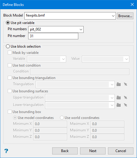
From the Block Model drop-down, select a block model file. Alternatively, click Browse... to located the required file.
You can then select the variable you want to base your contour on by entering the pit information, or by using the standard block selection criteria.
-
If you select Use pit variable, enter the following details:
-
Pit numbers: Select the variable that contains all of the pit numbers from the drop-down list.
-
Pit number: Enter the number of the pit that you want to base your contouring on.
-
-
If you select Use block selection configure the following options:
-
Mask by variable
Select the Mask by variable checkbox to restrict the blocks by a block model variable. You will need to select the variable and value to mask by from the Variable and Value drop-down lists.
Example: To restrict blocks to those where Material equals Ore, select Material as the variable and
Oreas the value. The block model variable may be numeric, such as the grade variable Au or character, such as Geology variables. -
Use test condition
Select the Use test condition checkbox to use a further constraint upon a numeric block model variable and enter the condition in the Condition field. The maximum size of the condition is 132 alphanumeric characters.
Refer to the appendix, Operators and Functions, for a full list of available operators and functions.
Example: To select only blocks that have an iron value greater than 10.0, you would select the Use condition checkbox and enter
Fe GT 10.0in the Conditions field. -
Use bounding triangulation
Select the Use bounding triangulation checkbox to restrict the blocks by a triangulation. Select the bounding triangulation to use from the Triangulation drop-down list, or click Browse... to select a triangulation from a location other than your working directory.
Note: This option is not applicable to open or 2D triangulations.
- Use bounding surfaces
Select the Use bounding surfaces checkbox to restrict the blocks by bounding surfaces. Select triangulations from the Upper triangulation and Lower triangulation drop-down lists, or click Browse... to select triangulations from a location other than your working directory.
-
Use bounding box
Select the Use bounding box checkbox to restrict the blocks by a box. Choose either Use model coordinates or Use world coordinates, then enter the minimum and maximum X, Y, and Z coordinates as opposite vertices of the bounding box.
Note: If the block model origin is set at 0,0,0, then select Use world coordinates for the minimum and maximum X, Y, and Z coordinates. If the block model origin is set at real world coordinates, then enter coordinates for the bounding box that are offset a certain distance from the origin. The distance of offset will be determined by the dimensions of your bounding box. It will be the distance to the minimum and the distance to the maximum X, Y and Z from the origin of the block model.
-
-
Click Next to open the Define Benches panel.
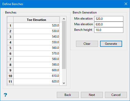
Bench Generation
If you selected the selected the Contour existing block model option, the minimum and maximum bench elevations will automatically be calculated. You will just need to enter the Bench height, which defines the height of a single bench.
If you did not selected the Contour existing block model option, you will need to specify the Min elevation, Max elevation, and Bench height. You can edit these settings later, but the pit designer needs at least two benches to work with.
Tip: It is a good idea to round these numbers since the exact elevations from the block model will be used to populate these fields. The pit designer can easily handle any numbers you choose, however, future reports based on the resulting design may be easier to deal with. For example, in the image below the initial elevations were from 523.4 to 628.7, but were rounded to 520.0 and 630.0 respectively.
After the elevation and bench height information has been entered:
-
Click Generate to populate the Benches table automatically.
-
Click Clear if you need to delete all entries in the table.
-
Click Next to open the Process Contours panel.
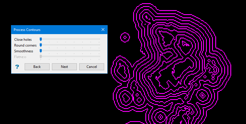
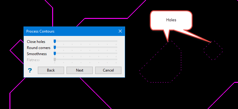
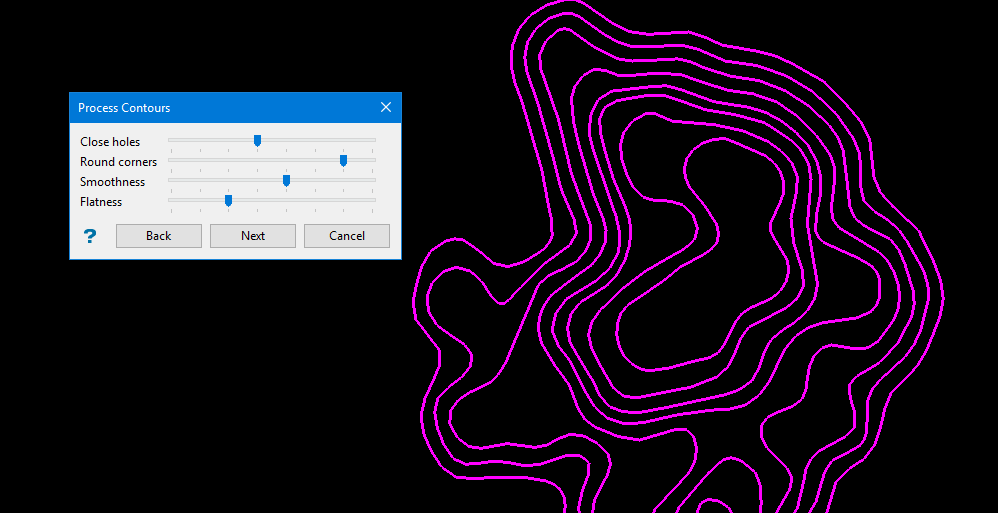
On the Process Contours panel, set the following parameters by dragging their sliders:
-
Close holes: The results from the pit optimiser will leave behind certain areas that it does not consider worth mining. These holes are represented by dashed lines. By zooming in you will be able to see them, if they exist. Using the Close holes slider control, you can adjust the sensitivity that determines which blocks will be included in the final pit design. As you increase the setting, more blocks will be included.
-
Round corners and Smoothness: Use these controls to remove blocks by smoothing the contours.
-
Flatness: The Smoothness control smooths the line by adding splines, which can dramatically increase the number of points in a line. Use the Flatness control to filter out some of the points.
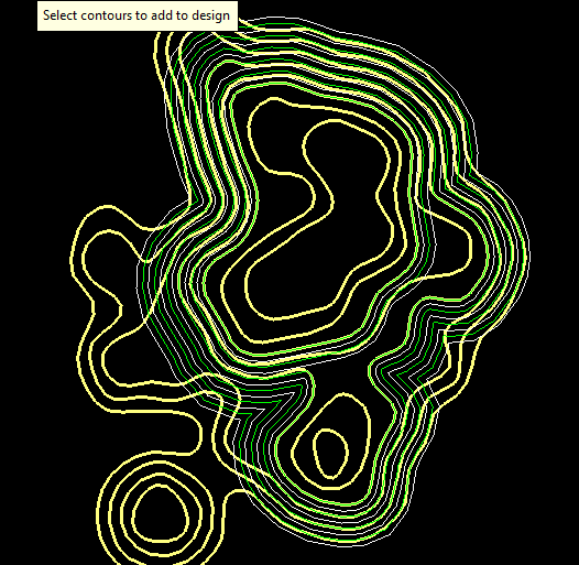
When you are satisfied with the results, click Next.
Select the contour lines you want to import into the pit designer to become seed strings. Click on a string to select it, and a preliminary pit design will be created. If you make a mistake or wish to select a different line, simply click on the string again to deselect it.
You can add as many lines as you want, but it is recommended that you only add a couple.
Right-click to confirm your choice to import the contour lines as seed strings.
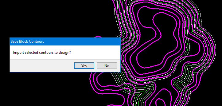
Selecting Yes will bring in the selected contours as seed strings and display the Pit Designer toolbar menu with different editing functions.
Designer tools
Details of each tool are given below the table.
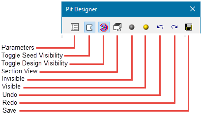
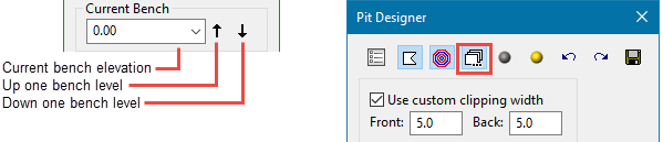
The menu panel allows you to edit the strings and set the clipping width for viewing the strings in section view.
Note: The parameters for setting the clipping width will display when you click the  button for Section View.
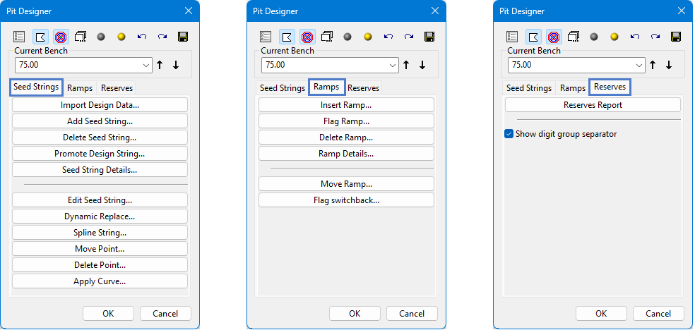
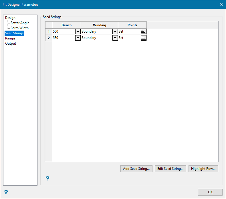
Seed Strings tab
| Tool | Function |
|---|---|
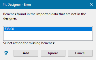
| Import Design Data |
This will allow you to select a design string from the screen and import it into the Auto Pit Designer as a seed string. After a string has been selected, you will be asked to confirm your selection by showing the following panel before it is committed to the pit design data.
|
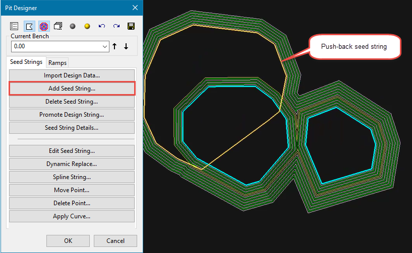
| Add Seed String | This will allow you to draw an initial polygon representing the pit floor or top surface boundary. After the boundary polygon has been created, the Auto Pit Designer will use it as the starting point for the pit. |
| Delete Seed String | This allows you to delete a seed string. Deleting a seed string will also remove the design data associated with that string. |
| Promote Design String | This will allow you to convert a bench to seed string. It is reasonably common to modify parts of the design as the pit projections and ramp design proceed up/down the overall pit. |
| Seed String Details |
This will open main panel, allowing you to view the details of a seed string and make edits from there.
|
| Edit Seed String | This allows you to edit a seed string by adjusting the location of points along the string. It uses the same methods as those used when editing a string with the standard polyline editing tools from the Design menu. |
| Dynamic Replace | This allows you to edit a seed string by applying a spline to a selected section of the string. |
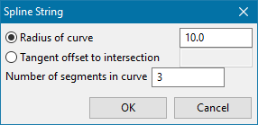
| Spline String | This will apply a spline to the entire string, adjusting the smoothness of the curves. |
| Move Point | Use this to click on a section of a seed string, then adjust the point location. |
| Delete Point | This allows you to delete one or more points along a string by first selecting the string, then deleting a selected point. |
| Apply Curve |
This allows you to apply a radius to a point by adding a selected number of points, thereby adjusting the smoothness of a curve.
|
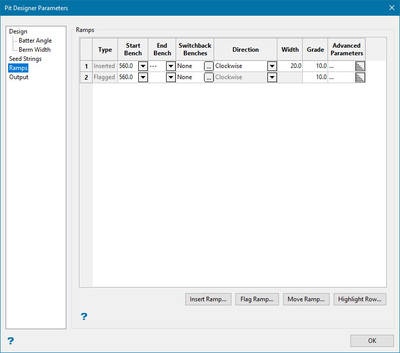
Ramps tab
| Tool | Function |
|---|---|
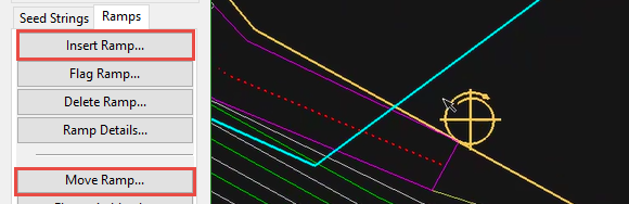
| Insert Ramp | This allows you to create a ramp by selecting the starting point of the ramp anywhere along the seed sting. |
| Flag Ramp | This tool is for specifying a specific segment of the seed string to be the start of a ramp. |
| Delete Ramp | This allows you to delete a ramp. |
| Ramp Details |
This will open main panel, allowing you to view the details of a ramp and make edits from there.
|
| Move Ramp | This allows you to move the ramp by dragging the spiral anywhere along the seed string, viewing the results. |
| Flag Switchback | This allows you to create a switchback on the ramp. |
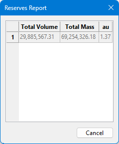
Reserves tab
Click the Reserves Report button to display the Reserves Report. The result is displayed in a dynamic panel after reserves are run from the main interactive panel.
One of the differences between this tool and other pit design tools is that you will not be drawing the toes and crests of the pit directly. Instead, you will be creating a recipe formed of seed strings that will turn into your design.
If you are not using the option to contour an existing block model, you will need to draw the seed strings yourself. Begin by clicking Add Seed String. This will allow you to draw an initial polygon representing the pit floor or top surface boundary. After the boundary polygon has been created, the Pit Designer will use it as the starting point for the pit and build the initial design.
If you selected the projection direction to go upwards, then the polygon drawn as the seed string will act as the pit bottom. If you selected the projection direction to go downwards, then the polygon will act as the top boundary to the pit.
Use the Edit Seed String, Delete Seed String, and Seed String Details buttons to make changes to the seed string. When an edit has been made, everything will update automatically allowing you to view the results immediately.
For additional information, see Modify Pit Design.
Boundary strings and hole strings are incorporated differently. Boundary seed strings in a pit contain rock on the outside and void inside (similar to hole strings in a dump). Hole strings in a pit contain rock on the inside and void outside (similar to boundary strings in a dump). Hole strings must be placed inside boundary strings to have an effect on the model.
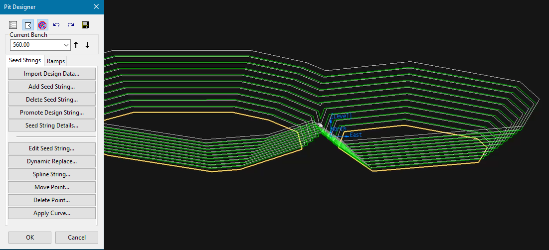
You can add more than one seed string. As more seed strings are added and a pit is created, the multiple pits will merge together, as shown below.
If you want to add a push-back on a higher elevation, click Higher Bench to highlight the bench elevation needed, then draw another seed string to define the outline of the push-back. Notice that there is no need to follow the contours of the existing pit. The push-back seed string is simply drawn to the edge of the bench and then cuts across to the other side. The new seed string is unioned into the design to form the flat, push-back area.
Ramps
To create a ramp, click Insert Ramp, then select the starting point of the ramp anywhere along the seed sting.
The start of the ramp will be represented by the spiral with cross-hairs, and show the direction of rotation. You can move the ramp by clicking Move Ramp and dragging the spiral anywhere along the seed string, viewing the results.
However, if you want to have more control over the design, begin by designing the beginning of the ramp into the seed string, then apply a flag. Flag Ramp is for specifying a specific segment of the seed string to be the start of a ramp.
The design will apply the width of the segment to the ramp.
Create a switchback on the ramp by clicking Flag Switchback, then selecting the elevation along the existing ramp that you want the switchback to occur.
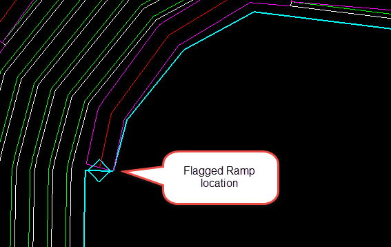
Moving a flagged ramp directly is not recommended. Instead, redraw the seed string first with the Edit Seed String button. You will then have the diamond flag symbol floating in space but not attached to the seed sting. Then use the Move Ramp button to move the ramp flag to the new location.
Saving your work
When you have a design that you want to keep, click Save to display the Pit Designer Parameters panel.
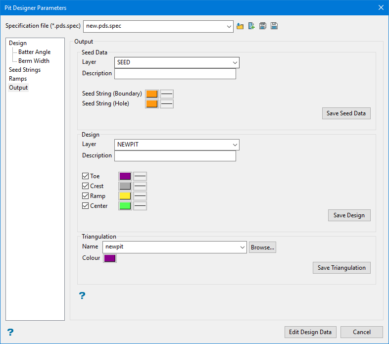
Using this panel, you can save your seed strings, design data, and the resulting triangulation.
Modify Pit Design
After you have drawn your seed strings and inserted a ramp, the basic process of building the pit design will be completed. The majority of your time will be spent modifying the initial design. This can be done while seeing the results of your changes updated automatically after each edit, eliminating the need to start from the beginning if something is not exactly how you want it.
For further information see Modify Pit Design.
