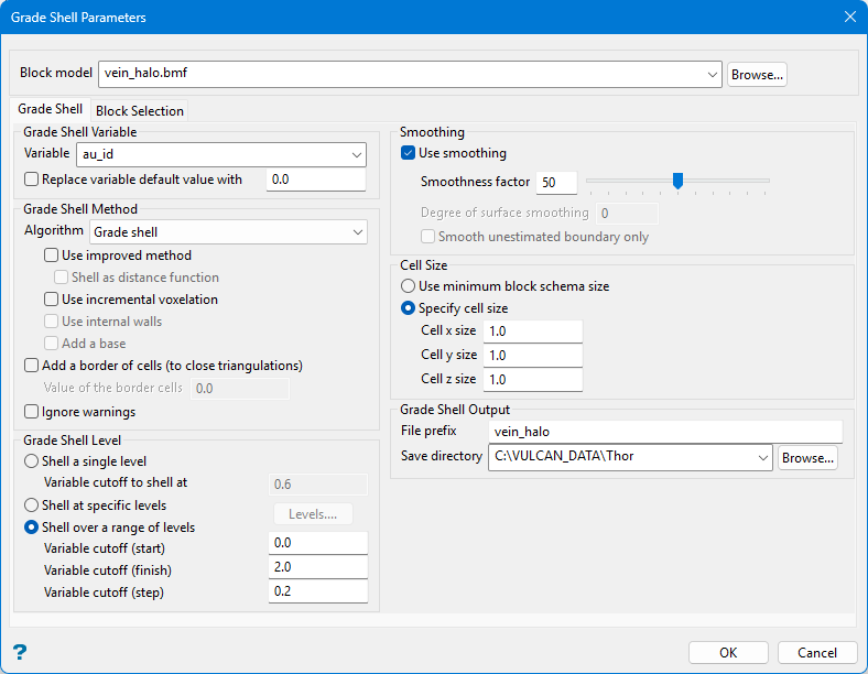
Grade Shells
Use the Grade Shells option to view areas of the block model above a particular cut-off grade.
Note: The calculations are made at the finest resolution of the smallest sub-block scheme in the model. The command line prompt -z will cause the executable to ignore insignificant zeros in lever parameter to set the name of the triangulation.
Create grade shells as follows:
-
On the Block menu, point to Viewing, and then click Grade Shells to display the Grade Shell Parameters panel.
-
Select a block model from the Block model drop-down or click Browse... to load a model from a different location.
-
Set the Grade Shell tab parameters per your requirements, as follows:
-
Under Grade Shell Variable:
-
Enter a Variable for which the grade shell is created, or select one from the drop-down.
-
(Optional) Select Replace grade variable default value with and enter a value.
Example: If the default value is '-99.0', then it could be replaced by '0.0' to ensure that the weighted average is correctly calculated.
-
-
Under Grade Shell Method, select one of the following algorithms from Algorithm from the drop-down list:
-
Use grade shell
Similar to the Use exact block boundary algorithm option except that, instead of a triangle at the edge between blocks, it projects onto a plane at a distance where the actual cut-off occurs.
-
Use exact block boundary algorithm
Produces triangles at the boundary of blocks where there is a block above or a block below the specified cut-off.
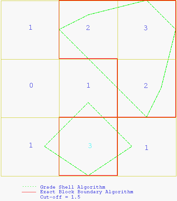
Figure 1: Grade Shell/Exact Block Boundary Algorithm
-
Compute top of exact boundary
Create the top surfaces of the block model's exact boundary based on the range of levels on which you are shelling.
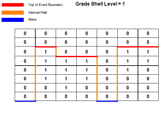
Figure 2: Compute Top of Exact Boundary Method (Sectional View)
-
Compute bottom of exact boundary
Create the bottom surfaces of the block model's exact boundary based on the range of levels on which you are shelling.

Figure 3: Compute Bottom of Exact Boundary Method (Sectional View)
-
-
Also under Grade Shell Method, select any of the following options:
-
Use improved method
The grade shelling method occasionally produces a surface with a problem. The improved method is designed to resolve these problems in certain instances. The improved method includes shell assistance, and is less prone to have a broken surface.
bmarchv2is the improved method. -
Shell as distance function
This option determines whether the values above the threshold or below the threshold are considered to be the solid. In the usual case, the values above the threshold are the solid and if it goes up to the boundary it caps it off. Select this function to use the information below as the solid instead.
-
Use incremental voxelation
Select to allocate memory for only one Z level of the grid. The memory is then moved incrementally through the data to produce the grade shell.
NoteThe block model will be reloaded for each Z level. Although this method results in slower execution time, it avoids memory problems.
If the Use incremental voxelation checkbox is not selected, then a voxel grid will be allocated for the extent of the block model (down to the smallest sub-block size). This can result in a lack of memory.
-
Use internal walls
Select to construct the grade shell's internal or side walls.
-
Add a base
Select to construct the base of the actual shell's internal or side walls.
-
Add a border of cells (to close triangulations)
Select to close the resulting triangulations at the boundaries.
-
Ignore warnings
Select this checkbox if you want to smooth the resulting contours and select the Smoothness factor between 0 (least) and 100 (most).
-
-
Under Grade Shell level, select one of the following options:
-
Shell a single level
Select this option to shell a single level. Select the Variable cutoff to shell at from the drop-down or enter a value.
-
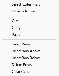
Shell at specific levels
Select this option to shell specific levels, then click Levels... to open the Enter Specific Levels panel. Select the required cut-off levels and click OK.
TipThis panel utilises grid controls to manage the grid information that allow you to perform options such as hiding columns, cutting, copying, and pasting cells, and inserting and deleting rows. Right-click in the grid area to display the context menu. Descriptions of the available options are listed below.
 Grid Control Options
-
Use the Select Columns... option to choose which grid columns to display in the panel, and optionally save the selection to a template for future use.
-
Select cells and click Hide Columns to hide the respective columns directly.
-
Select cells and use the Cut, Copy, and Paste options to duplicate or move cell entries.
-
Select a cell in a row of interest and use the insert and delete row options to manage the records in the grid.
-
Click Clear Cells to clear the contents of a selection.
-
-
-
-
(Optional) Under Smoothing, select Use smoothing, then configure smoothing parameters as follows:
-
Enter the Smoothness factor or set it with the slider from 0 (least) to 100 (most).
-
Enter a value for Degree of surface smoothing.
-
(Optional) Select Smooth unestimated boundary only to limit smoothing to
-
-
Under Cell Size, select one of the following options:
-
Use minimum block schema size
Use the minimum block schema size when defining the cell size of the cube used in the marching cube algorithm. This option replicates the method used in earlier versions of Vulcan.
-
Specify cell size
Specify the size of the cells used in the marching cube algorithm. Enter the x, y and z cell sizes.
The specified cell size must be larger than the minimum block size. If the cell size is less than the block size, then the minimum block size will be used instead. If the cell size is larger than the minimum block size, then weight averaging based on volumes will be used to calculate the grade value for the cell.
A cube with large cube extents will result in fewer points and triangles within the resultant grade shell triangulation. This will, however, result in a grade shell that is not as accurate as one created using smaller cube extents.
-
-
Under Grade Shell Output enter the a name for the resulting triangulation file in File prefix and enter the file path in Save directory. Alternatively, click Browse... to select a new path.
By default, the name of the current block model will be displayed. The full name is <prefix>_<variable>_<cutoff>.00t.
-
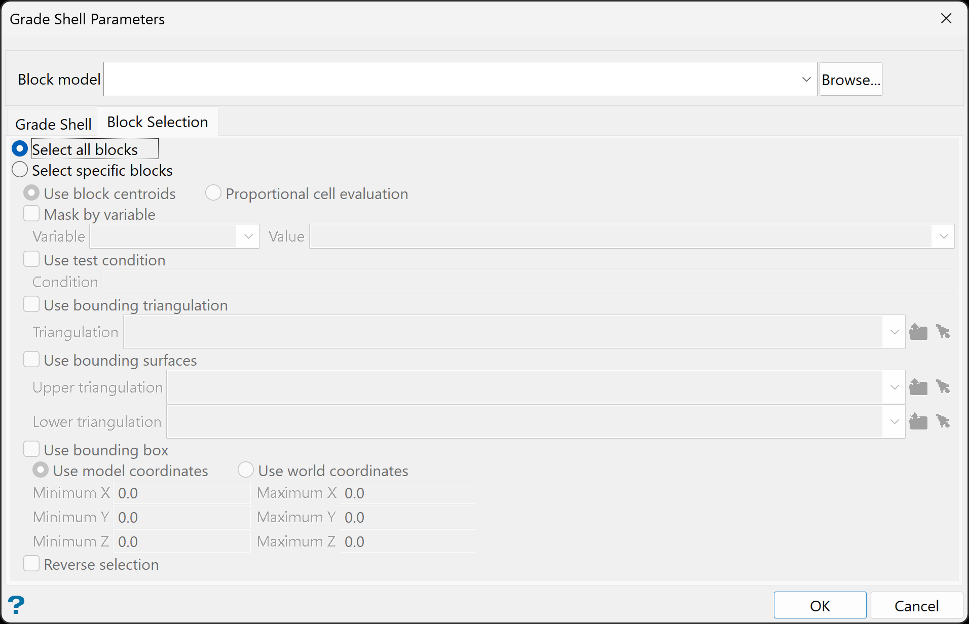
Select the Block Selection tab, then choose between the following options:
-
Select all blocks and go to step 8.
Or
-
Select specific blocks, then set the remaining options as follows:
-
Select Use block centroids to include any blocks whose centroids are within the region (if any are provided in the block selection tab).
Or
-
Select Proportional cell evaluation to include all blocks that touch the region, and evaluate reserves according to the proportion of the block's volume that lies within the region. Proportional cell evaluation calculates and reports the exact proportion of a block within a solid triangulation. Only blocks that are fully outside the region are ignored in proportional cell evaluation mode.
-
Mask by variable
Select the Mask by variable checkbox to restrict the blocks by a block model variable. You will need to select the variable and value to mask by from the Variable and Value drop-down lists.
Example: To restrict blocks to those where Material equals Ore, select Material as the variable and
Oreas the value. The block model variable may be numeric, such as the grade variable Au or character, such as Geology variables. -
Use test condition
Select the Use test condition checkbox to use a further constraint upon a numeric block model variable and enter the condition in the Condition field. The maximum size of the condition is 132 alphanumeric characters.
Refer to the appendix, Operators and Functions, for a full list of available operators and functions.
Example: To select only blocks that have an iron value greater than 10.0, you would select the Use condition checkbox and enter
Fe GT 10.0in the Conditions field. -
Use bounding triangulation
Select the Use bounding triangulation checkbox to restrict the blocks by a triangulation. Select the bounding triangulation to use from the Triangulation drop-down list, or click Browse... to select a triangulation from a location other than your working directory.
Note: This option is not applicable to open or 2D triangulations.
- Use bounding surfaces
Select the Use bounding surfaces checkbox to restrict the blocks by bounding surfaces. Select triangulations from the Upper triangulation and Lower triangulation drop-down lists, or click Browse... to select triangulations from a location other than your working directory.
-
Use bounding box
Select the Use bounding box checkbox to restrict the blocks by a box. Choose either Use model coordinates or Use world coordinates, then enter the minimum and maximum X, Y, and Z coordinates as opposite vertices of the bounding box.
Note: If the block model origin is set at 0,0,0, then select Use world coordinates for the minimum and maximum X, Y, and Z coordinates. If the block model origin is set at real world coordinates, then enter coordinates for the bounding box that are offset a certain distance from the origin. The distance of offset will be determined by the dimensions of your bounding box. It will be the distance to the minimum and the distance to the maximum X, Y and Z from the origin of the block model.
- Reverse selection
Select Reverse selection if you want to exclude the selected blocks within the slice. If this option is not selected, the entire block is included within the slice by default.
-
-
-
Click OK.
The grade shell triangulations are then generated.
