Create Section
Use the Create Section option to create a cross-sectional 3D view with a specified dip and width of view.
Tip: Click the ![]() (Show Overview) button from the Graphics toolbar to open an overview window showing the plan location of the section.
(Show Overview) button from the Graphics toolbar to open an overview window showing the plan location of the section.
Instructions
On the View menu, click Create Section.
Follow these steps:
-
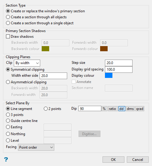
Choose a Section Type.
-
Create or replace the window's primary section: Select this option to create a primary section. This option is equivalent to the View > Change View > Section option with some additional items for displaying this section, such as being able to select the shadow colour, and options for the Clipping Planes. The primary section will disappear when you click the
 (Reset) button.
If you create a new primary section in the same viewport, then the previous section is replaced. Your view is changed to be perpendicular to the plane when you create a primary section. This is why the overview window is useful.
Note: Only primary sections can have shadows. The Annotate checkbox and Section name text box will be unavailable if this option is selected.
-
Create a section through all objects: Select this option to create a non-primary section. The number of non-primary sections that you can create is limited by the clipping that you require (and possibly by your graphics card's OpenGL implementation - for more information see the OpenGL website). Unlike primary sections, your view is not changed to be perpendicular to the plane when you create a non-primary section.
Non-primary sections can be used for intersecting with volumes (or triangulations) to create intersection highlights. For more information see Highlight Intersections
 .
.
-
Create a section through a single object: Select this option to create a non-primary section.
Note: When you select this option, the other objects are not clipped nor are their intersections with planes calculated. However, when you create a section through all objects the clipping plane affects everything.
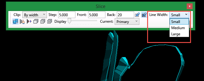
TipSometimes viewing a triangulation in section view can be difficult if you happen to be viewing the triangulation edge on. To make it easier to see, use the Slice toolbar Line Width tool to adjust the thickness of the intersection line.
-
-
Select Draw Shadows to shadow the data that falls outside the section. Shadows are only displayed if you choose to clip By width (see below).
-
Backwards width/Forwards width: Specify the width of data that will be shadowed out either side of the section. The backwards width and the forwards width do not have to be the same value.
-
Backwards colour/Forwards colour - Specify the colour of the backwards and forwards shadows.
-
-
Use the Clip drop-down list to specify the type of clipping plane to be used with the section. There are four options:
-
By width: The view of your section will only include the width of the section, along with any shadows if you have created a primary section.
-
Forwards: The view of your section will include everything in front of your section.
-
Backwards: The view of your section will include everything behind your section.
-
No clipping: The view of the section will include everything.
-
-
Enter the Step size. This is the distance that is moved each step when moving the section through space.
Note: To move the section through space, use the
 (Slice Forward) or
  (Slice Backwards) buttons on the Slice toolbar. Alternatively, you can also click the
  (Align View With Current Slicing Plane) button and use the up and down arrows to move through space.
 -
Choose whether you want Symmetrical or Asymmetrical clipping. When you choose to create a section By width, you can specify that the section is symmetrical (i.e. the same distance forwards or backwards), or asymmetrical (i.e. different distances forwards and backwards.
-
In the Display grid spacing textbox, enter the spacing of the grid used to represent the plane. To control the translucency of the grid, use the Display slider bar on the Slice toolbar.
Click the Display colour button to specify the colour of the grid that represents the plane.
-
Select the Annotate checkbox and enter a Section name to annotate a point on the section plane. This name will be displayed in the drop-down list on the Slice toolbar. The annotation value will change as you move the section through space. The size of the annotation is directly proportional to the Display Grid Spacing setting.
-
Under Select plane by, select the required viewing plane option from the following:
 Line segment
Select this option to define the plane by selecting an existing line and specifying the dip. Only design strings may be picked and it is not possible to pick a line in an underlay. The direction of the view, and therefore the direction of the stepping, depends on the digitised sequence of the line. The digitised sequence of the line can be reversed using the Design > Object Edit > Reverse option.
2 Points
Select this option to define the plane by digitising two points and specifying the dip. To locate a point precisely, use the
 (Snap to Objects) or
  (Snap to Points) mode on the Digitise toolbar. Points may be snapped onto underlays, such as block model slices or triangulations. If you use mode
  (Indicate) to select the points, then the points have the current default Z value.Dip
If you choose to select your plane by either a line segment or 2 points, then you must indicate a dip. The dip is the angle of the section from horizontal, and may be entered in your choice of the following units: % (percentage gradient), ratio (gradient as a ratio) dd (decimal degrees), dms (degrees-minutes-seconds) or grad (gradians)
Valid dip angles are between
-90and90degrees or equivalent in the chosen units.3 Points
Select this option to define the plane by digitising 3 points. To locate a point precisely, use the
(Snap to Objects) or (Snap to Points) mode on the Digitise toolbar. Points may be snapped onto underlays, such as block model slices or triangulations.Selecting this option to define explicitly the location and orientation of a plane by indicating 3 points. The first two points define the bearing of the plane, and the third point defines the dip of the plane.
Guide centre line [section is normal to line]
Select this option to define the plane by selecting a centre line. W tag of the points of the picked centre line can be employed to pass section width.
Tip: To achieve the best results for the following three methods, Easting, Northing and Level, use the
 (Zoom Data Extents) button on the Graphics toolbar, which allows all of the graphics to be viewed.Easting
Select this option to enter a specific Easting (X) value. There are two ways to enter the Easting value: you can enter it directly into the text box, or you can select the Digitise button, which to select a point from the viewing window. The resulting section will face an easterly direction.
Northing
Select this option to enter a specific Northing (Y) value. There are two ways to enter the Northing value; you can enter it directly into the text box, or you can select the Digitise button, which to select a point from the viewing window. The resulting section has a constant northing value.
Level
Select this option to enter a specific Level (Z) value. There are two ways to enter the Level value; you can enter it directly into the text box, or you can select the Digitise button, which enables you to select a point from the viewing window. The resulting section has a constant level value.
To locate a point precisely, use the
(Snap to Objects) or (Snap to Points) mode on the Digitise toolbar. Points may be snapped onto underlays, such as block model slices or triangulations. You will need to select this point before completing the panel. The panel will collapse while you select the point.Facing
Select the orientation of the section view. The drop-down list contains different options depending upon the method used to select the plane, per the table below. The first choice in the drop-down list is the default orientation.
Method Orientation Line Segment Point Order
Reverse Point OrderTwo Points Left to right
Right to leftThree Points Clockwise
AnticlockwiseGuide centre line Point Order
Reverse Point OrderEasting East
WestNorthing North
SouthLevel Down
Up -
Click OK.
