Create
Linking an Object
Use the Create option to link an object to a database, text file, shell command or macro. These links become attributes of the object and are stored as part of the object in the open design database, that is, the links are not stored as separate entities. Up to 60 links per polygon/object are possible.
This option can be used to connect an object with a database containing information about the object.
Example: A series of polygons might represent property boundaries. Each of these polygons can be linked to a database that contains information, such as the owner's name and contact details. You can then use the Inquire option to display the information in the Report Window. Another use for this kind of database would be for tenement data. The database could contain ownership details, expiry details etc., and the linked polygons could be the tenement boundaries.
The List option (under the Analyse > Details submenu) can be used to list an object's details. This includes the number of links, name of links, type of links and the files, databases and commands that are attached.
The Inquire option (under the Analyse > Attribute Data submenu) is used to activate the link for each object. If more than one link is created per object, the you will be prompted to choose the appropriate link to activate.
Instructions
On the Analyse menu, point to Attribute Data, and then click Create.
Select the object.
The Link type dialog box is then displayed. The Link type dialog box contains the following link types;
Text File
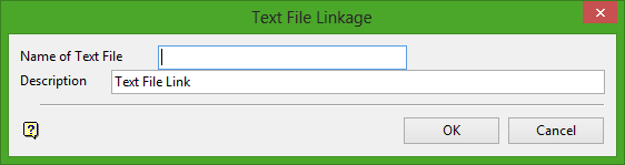
Name of Text File
Enter the name, including extension, of the file. The maximum size is 20 alphanumeric characters.
Description
Enter an optional 20 alphanumeric character description of the link.
Click OK.
Select another object. Cancel when finished creating links.
Use the Inquire option to activate the link. The contents of the text file displays in the Report Window.
Isis DB
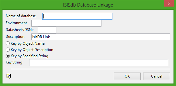
Name of database
Enter the identifier ( <sdi> ) in the case of design databases, <odi> in the case of non-design databases) of the database to which you want to link the object. You will need to specify the design (datasheet) and the environment to which the database belongs. The project code of the database is assumed to be the same as the currently open database.
Description
Enter an optional 40 alphanumeric character description of the link.
You can key by object name, description or a string (maximum size 40 alphanumeric characters). When you activate the link (using the Inquire option) the database is searched for a key that matches your key and all of the records relating to that key are displayed in the Report Window.
Select the key by method, that is, by object name, object description etc.
Click OK.
Select another object. Cancel when finished creating links.
Use the Inquire option to activate the link. All of the records relating to the specified key are displayed in the Report Window.
Execute
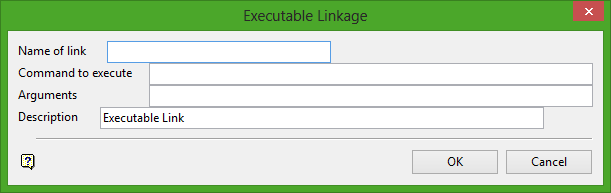
Name of link
Enter the name of the link. The maximum size is 20 alphanumeric characters.
Command to execute
Enter the command to execute. The maximum size is 40 alphanumeric characters.
If the path to the executable is longer than 40 alphanumeric characters, then add the path to your PATH environment variable.
Example: For wordpad.exe, add c:\Program Files\Windows NT\Accessories to your PATH variable. Keep in mind that the entries in the PATH environment variable need to be separated by semicolons (;). You will also need to restart Vulcan for the changes to PATH to take effect.
Arguments
Enter any arguments that you want to use with the executable. The maximum size is 40 alphanumeric characters. Arguments can be an actual argument, for example -l, a file name or a combination.
Example: tq3.00p_plot 11
The Arguments field is just an additional line. You could put the entire instruction in the Command field, for example plot tq3.00p_plot 11. Ending an instruction with a space and an & (ampersand) will cause the job to run in the background.
Description
Enter an optional 40 alphanumeric character description of the link.
Click OK.
Select another object. Cancel when finished creating links.
Use the Inquire option to activate the link. The command will be executed.
Macro
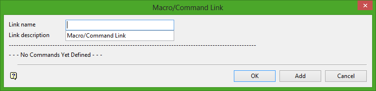
Link Name
Enter the name of the link. The maximum size is 20 alphanumeric characters.
Link Description
Enter an optional 40 alphanumeric character description of the link.
Once a command has been created, it will be placed as a radio button in the bottom half of the panel and extra buttons are added to the panel, which allow you to insert, edit, delete and execute commands. For more information on managing your commands refer to Macro/Command List.
Select Add to add a command. Once selected, the Select a Command dialog box displays. Select the required macro command.
| PICTURE | Display an image stored in your working directory. |
| PICTURE_SCR | Display a picture in a fixed screen position. |
| PICTURE_ABS | Display a picture at an absolute position. |
| SOUND | Play a sound file. |
| EXECUTE | Execute a command. |
| LOAD_LAYER | Load a layer. |
| REMOVE_LAYER | Remove a loaded layer. |
| LOAD_MODEL | Load a grid model or triangulation. |
| REMOVE_UNDER | Remove underlays. |
| EDIT | Edit a text file. |
| BROWSE | View, in the Report Window, the contents of a text file. |
| LOAD_TEXT | Load onto the screen the contents of a text file. |
| Isis_DB | View, in the Report Window, records relating to a selected database key. |
| WALK | Walk along a nominated path. |
| VISIBILITY | Alter the visibility of layers and underlays. |
| WAIT | Add a pause to the running of the macro. |
| STEP_ON | Add the ability to step through the macro. |
| STEP_OFF | Remove the ability to step through the macro, should only be used if the Step On option was used. |
| CLEAR | Remove objects from the screen. |
When creating macros, base (meta) names can be used whenever you enter a command. Base names allow you to run a single macro over several objects without having to edit the macro each time.
For example, running a macro that puts a picture called poly.rgb on the screen when you select an object called poly, would require editing of the macro if you then wanted to use picture poly2.rgb for object poly2.
Using a base name rather than the real name will make the system search for the corresponding .rgb file, that is, an .rgb file with the same name as the object. Base names take the form of {$<basename>}.<ext> where <basename> = an allowable base name and <ext> = file extension, for example {$NAME_L}.rgb. Refer to Base Names for a list of acceptable names.
Picture
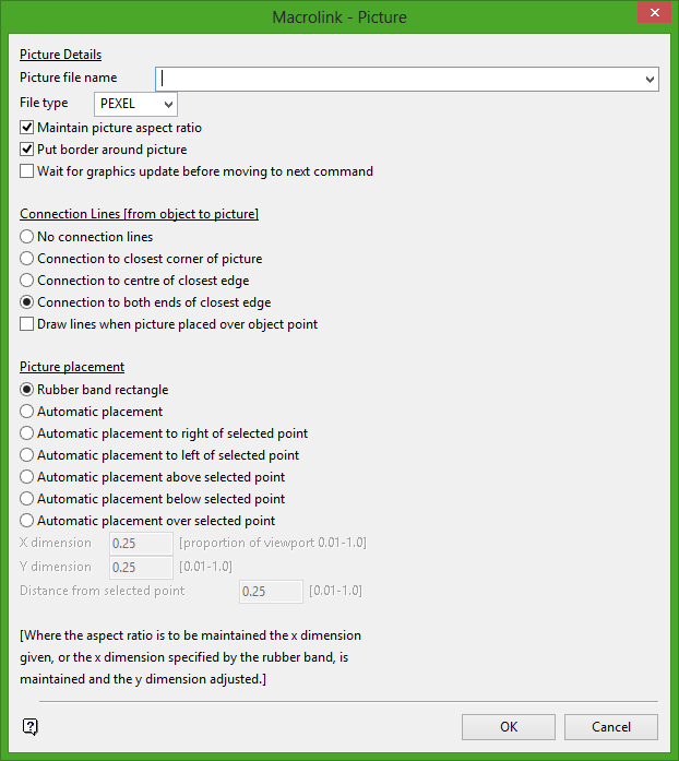
Picture Details
Picture file name
Enter or select from the drop-down list the name and file extension of the image file or the base name.
File Type
Select the image format, for example RGB or Pexel.
Maintain picture aspect ratio
Select this check box if you want to maintain the height and width ratio of the image.
Put border around picture
Select this check box if you want to place a border around the picture.
Wait for graphics update before moving to next command
Select this check box if you want to wait for the graphics to update before continuing on to the next command.
Connection Lines (from object to picture)
No connection lines
Select this option if no connection lines between the object and the picture are required.
Connection to closest corner of picture
Select this option to create a connection line between the object and the closest corner of the picture.
Connection to centre of closest edge
Select this option to create a connection line between the object and the centre of the closest edge of the picture.
Connection to both ends of the closest edge
Select this option to create connection lines between the object and both ends of the closest edge of the picture.
Draw lines when picture placed over object point
Check this box when connection lines are required only when the picture is placed over the top of an object point.
Picture placement
Rubber band rectangle
Select this option to place the picture manually by using a rubber band rectangle.
Automatic placement
Select this option to place automatically the picture on the screen.
Automatic placement to right of selected point
Select this option to place automatically the picture to the right of selected point. (You will be asked to select the point on the screen when this panel is completed.)
Automatic placement to left of selected point
Select this option to place automatically the picture to the left of selected point. (You will be asked to select the point on the screen when this panel is completed.)
Automatic placement above selected point
Select this option to place automatically the picture above the selected point. (You will be asked to select the select on the screen when this panel is completed.)
Automatic placement below selected point
Select this option to place automatically the picture below the selected point. (You will be asked to select the point on the screen when this panel is completed.)
Automatic placement over selected point
Select this option to place automatically the picture over the selected point. (You will be asked to select the point on the screen when this panel is completed.)
X dimension
Note: Applicable only if an automatic placement option is selected.
The value specified here is a proportion of the display window (screen area) in the X direction (horizontal). The value must be between 0.01 and 1.0, where 1 is the full width of the screen. A value of 0.25 would mean that the display uses a quarter of the screen area. The aspect ratio of the image is maintained in the Y-dimension when using this option.
Y dimension
Note: Applicable only if an automatic placement is selected.
The value specified here is a proportion of the display window (screen area) in the Y direction (vertical). The value must be between 0.01 and 1.0, where 1 is the full height of the screen. A value of 0.25 would mean that the display uses a quarter of the screen area. The aspect ratio of the image is maintained in the X-dimension when using this option.
Distance from selected point
Note: Applicable only if an automatic placement is selected.
Enter the distance between the point selected and the closest corner of the picture.
Click OK.
The Macro/Command panel is then redisplayed with your command appearing in the bottom half. Refer to Macro/Command list for information on managing your commands.
Pictures are loaded as underlays and can therefore be removed using the Remove Underlay command, or Remove Underlay ![]() on the Standard toolbar.
on the Standard toolbar.
Picture Screen
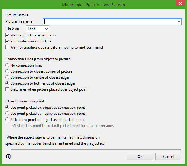
Picture Details
Picture file name
Enter or select from the drop-down list the name and file extension of the image file or the base name.
File Type
Select the image format, for example RGB or Pexel.
Maintain picture aspect ratio
Select this check box if you want to maintain the height and width ratio of the image.
Put border around picture
Select this check box if you want to place a border around the picture.
Wait for graphics update before moving to next command
Select this check box if you want to wait for the graphics to update before continuing on to the next command.
Connection Lines (from object to picture)
No connection lines
Select this option if no connection lines between the object and the picture are required.
Connection to closest corner of picture
Select this option to create a connection line between the object and the closest corner of the picture.
Connection to centre of closest edge
Select this option to create a connection line between the object and the centre of the closest edge of the picture.
Connection to both ends of the closest edge
Select this option to create connection lines between the object and both ends of the closest edge of the picture.
Draw lines when picture placed over object point
Check this box when connection lines are required only when the picture is placed over the top of an object point.
Object connection point
Use point picked on object as connection point
Select this option to select the point you chose on the object when creating the macro to be the connection point. Connection line(s), if applicable, will be drawn between the image and this point.
Use point picked at inquiry as connection point
Select this option to use the point picked at the Inquiry stage as the connection point. Connection line(s), if applicable, will be drawn between the image and this point.
Pick a new point on object as connection point
Select this option to pick a new point on the object to use as the connection point. Connection line(s), if applicable, will be drawn between the image and this point.
Make this point the default picked point for other commands
Select this check box to have the selected point used as the default point for other macro commands.
Click OK.
The Macro/Command panel is then redisplayed with your command appearing in the bottom half. Refer to Macro/Command list for information on managing your commands.
Pictures are loaded as underlays and can therefore be removed using the Remove Underlay command, or Remove Underlay ![]() on the Standard toolbar.
on the Standard toolbar.
Picture Abs
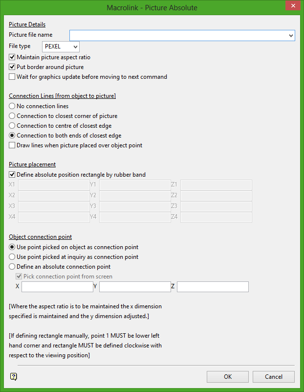
Picture Details
Picture file name
Enter or select from the drop-down list the name and file extension of the image file or the base name.
File Type
Select the image format, for example RGB or Pexel.
Maintain picture aspect ratio
Select this check box if you want to maintain the height and width ratio of the image.
Put border around picture
Select this check box if you want to place a border around the picture.
Wait for graphics update before moving to next command
Select this check box if you want to wait for the graphics to update before continuing on to the next command.
Connection Lines (from object to picture)
No connection lines
Select this option if no connection lines between the object and the picture are required.
Connection to closest corner of picture
Select this option to create a connection line between the object and the closest corner of the picture.
Connection to centre of closest edge
Select this option to create a connection line between the object and the centre of the closest edge of the picture.
Connection to both ends of the closest edge
Select this option to create connection lines between the object and both ends of the closest edge of the picture.
Draw lines when picture placed over object point
Check this box when connection lines are required only when the picture is placed over the top of an object point.
Picture Placement
Define absolute position rectangle by rubber band
Select this check box to use the rubber band to define the picture position. Uncheck this box to define XYZ coordinates for each of the four corner points of the picture.
Object connection point
Use point picked on object as connection point
Select this option to select the point you chose on the object when creating the macro to be the connection point. Connection line(s), if applicable, will be drawn between the image and this point.
Use point picked at inquiry as connection point
Select this option to use the point picked at the Inquiry stage as the connection point. Connection line(s), if applicable, will be drawn between the image and this point.
Pick a new point on object as connection point
Select this option to pick a new point on the object to use as the connection point. Connection line(s), if applicable, will be drawn between the image and this point.
Make this point the default picked point for other commands
Select this check box to have the selected point used as the default point for other macro commands.
Click OK.
The Macro/Command panel is then redisplayed with your command appearing in the bottom half. Refer to Macro/Command list for information on managing your commands.
Pictures are loaded as underlays and can therefore be removed using the Remove Underlay command, or Remove Underlay ![]() on the Standard toolbar.
on the Standard toolbar.
Sound
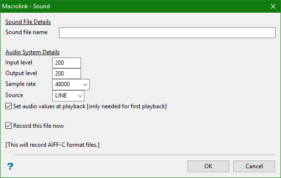
This panel to record and playback a sound file when the Inquire option is selected. The sound file is in AIFF format. Sound files are not applicable to NT platforms.
Sound File Details
Sound file name
Enter the name of the sound file (either existing or to record) or the base name. The input and output audio levels are measured as an arbitrary value between 0 and 255, where 0 is no volume, and 255 is full volume. These values should be adjusted for your preference.
Audio System Details
Input Level
Enter the audio input level value.
Output Level
Enter the audio output level value.
Sample Rate
Enter the sample rate. The sample rate is measured in bits per second (bps). The rates that are available are 8000, 11025, 16000, 22050, 32000, 44100 and 48000. The default rate is 48000, which is CD quality. Lowering the sampling rate will lower the quality, but it will also reduce the size of the sound data file. This in turn increases the speed of loading prior to playback. If the recording time is long, the sound file will be large. For sound files containing only speech, a lower sampling rate can be used.
Source
Enter the sound source from the list. The source can either be from LINE or MIC. If it is from LINE, it is read from an auxiliary device, such as a CD player. If it is from MIC, it is recorded from the microphone.
Set audio levels at playback
Select this check box to set the audio levels when the sound file is played back. The audio levels are arbitrary values between 0 and 255, where 255 is full volume, and 0 is no volume.
Record this file now
Select this check box to begin recording of the sound file on the completion of the panel.
Click OK.
The Macro/Command panel is redisplayed, with your command appearing in the bottom half. Refer to Macro/Command list for information on managing your commands.
Execute
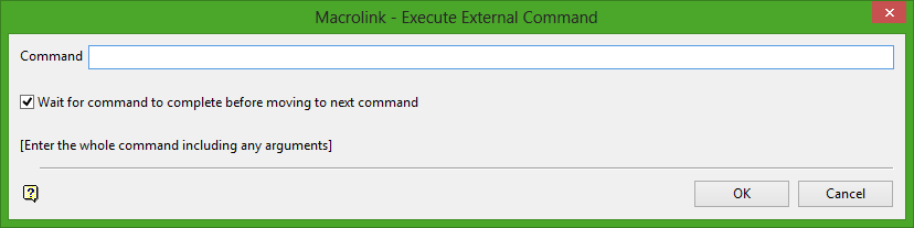
This macro command is similar to creating an Executable link. With this option, however, you can create a macro, which contains several commands, rather than just the one command.
Command
Enter the external command to execute, (including arguments) or the base name.
Wait for command to complete before moving to next command
Select this check box to wait for this command to be completed before any other command is executed.
Click OK.
The Macro/Command panel is redisplayed, with your command appearing in the bottom half. Refer to Macro/Command list for information on managing your commands.
Load Layer
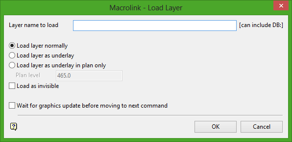
Layer name to load
Enter the name of the layer to load or the base name. The layer can be from another database. To do this, enter the database name (minus the dgd extension), a colon and the name of the layer.
Example: THORDESIGN:PEI
Load layer normally
Select this option to load the layer as normal.
Load layer as underlay
Select this option to load the layer as an underlay.
Load layer as underlay in plan only
Select this option to load the layer as an underlay, but only in plan view. Enter the plan level (RL) to ensure that the layer is loaded at the correct height.
Load as invisible
Select this check box to load the layer as invisible. The visibility levels can be changed by using the Visibility command (this option) or the Visibility menu under View.
Wait for graphics to update before moving to next command
Select this check box to wait for the graphics to update before continuing on to the next command.
Click OK.
The Macro/Command panel is redisplayed, with your command appearing in the bottom half. Refer to Macro/Command list for information on managing your commands.
Remove Layer
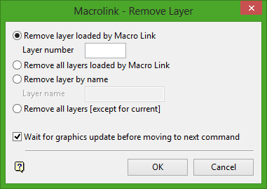
Remove layer loaded by Macro Link
Select this option to remove a layer previously loaded by the Load_Layer option. Enter the number of the layer to remove. Layer numbers are obtained from the Macro/Command Link panel. The numbers are located on the far right hand side of the panel, corresponding with the loaded layer. The numbers are defined as :L01, :L02, for Layer 1, Layer 2, in order of loading.
Remove all layers loaded by Macro Link
Select this option to remove any layer previously loaded by the Load_Layer option.
Remove layer by name
Select this option to remove a loaded layer by name. Enter the name in the area provided.
Remove all layers
Select this option to remove all layers except for the current layer.
Wait for graphics to update before moving to next command
Select this check box to wait for the graphics to update before continuing on to the next command.
Click OK.
The Macro/Command panel is redisplayed, with your command appearing in the bottom half. Refer to Macro/Command list for information on managing your commands.
Load Model
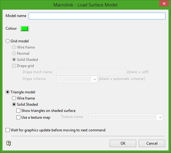
Model name
Enter the name of the model or the base name.
Colour
Choose the colour for the model
Grid Model
Select this option to load a grid model.
Wire Frame
Select this option to load the model as a wire frame.
Normal
Select this option to load model normally.
Solid Shaded
Select this option to load the model as a solid shaded object.
Drape Grid
Select this check box to drape a grid mesh over the model. Enter the name of the grid mesh and the scheme.
Triangle model
Select this option to load a triangulation.
Wire Frame
Select this option to load the model as a wire frame.
Solid Shaded
Select this option to load the model as a solid shaded object.
Show triangles on shaded surface
Select this check box to show triangles on shaded surface.
Use a texture map
Select this check box to apply a texture map to the model. Enter, or select from the drop-down list, the name of the texture.
Wait for graphics to update before moving to next command
Select this check box to wait for the graphics to update before moving on to the next command.
Click OK.
The Macro/Command panel is redisplayed, with your command appearing in the bottom half. Refer to Macro/Command list for information on managing your commands.
Remove Underlay
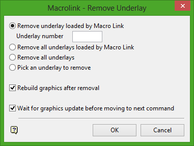
Remove Underlay loaded by Macro Link
Select this option to remove an underlay previously loaded by the Load_Layer (as underlay), Load_Model or the picture options. Enter the number of the underlay to remove. Underlay numbers are obtained from the Macro/Command Link panel. The numbers are located on the far right hand side of the panel, corresponding with the loaded underlay. The numbers are defined as :U01, :U02, for Underlay 1, Underlay 2, in order of loading. Pictures are also loaded as underlays.
Remove all underlays loaded by Macro Link
Select this option to remove any underlays previously loaded by the Load_Layer, Load_Model or the Picture options.
Remove all underlays
Select this option to remove all underlays from the screen.
Pick an underlay to remove
Select this option to pick the underlay from the screen to remove.
Rebuild graphics after removal
Select this check box to refresh the screen and rebuild the graphics after removal of the underlay(s).
Wait for graphics update before moving to next command
Select this check box to wait for the graphics to update before continuing on to the next command.
Click OK.
The Macro/Command panel is redisplayed, with your command appearing in the bottom half. Refer to Macro/Command list for information on managing your commands.
Edit
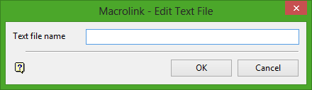
Text file name
Enter the name of the text file you want to edit when the link is activated.
Click OK.
The Macro/Command panel is redisplayed, with your command appearing in the bottom half. Refer to Macro/Command list for information on managing your commands.
Browse

Text file name
Enter the name of the text file you want to view when the link is activated.
Click OK.
The contents of the text file is then displayed in the Report Window when the link is activated.
The Macro/Command panel is redisplayed, with your command appearing in the bottom half. Refer to Macro/Command list for information on managing your commands.
Load Text
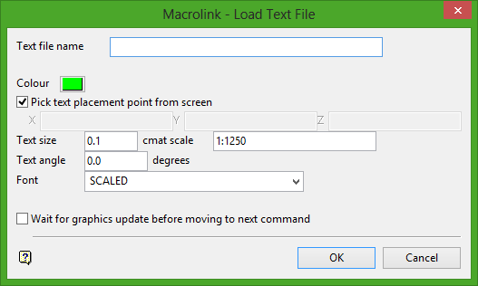
Text file name
Enter the (base) name of the text file to load when the object is chosen from the Inquire option.
Colour
Select a colour for the text.
Pick text placement point from screen
Select this check box to pick, from the screen, the origin of the text. Uncheck the box to define the origin by XYZ coordinates.
Text size
Enter the text size, in centimetres, for the text on a plot. Enter the map scale. The map scale, along with the text size, is used to determine the size of transformable text on the screen. For example, if the text size is set to 0.10 (10 cm) and the map scale to 1:1250, text will appear on the screen the same size as an object that is 125 units long. Changing the scale to 1:1000 results in the text appearing the same size as an object that is 100 units long. Changing the scale to 1:10 000 results in a text size of 1000 and so forth. Non-transformable text is always displayed the same size regardless of zoom or rotation effects.
Text angle
Enter the angle at which the text block appears. For example, 0° = horizontal (as normal text), 90°= vertical. Non-transformable fonts are always displayed on the screen horizontally. The text will appear at the correct angle on plots.
Font
Select a font for the text. Non-transformable fonts are Small, Medium, Normal and Large.
Wait for graphics update before moving to next command
Select this check box to wait for the graphics to update before continuing on to the next command.
Click OK.
The Macro/Command panel is redisplayed, with your command appearing in the bottom half. Refer to Macro/Command list for information on managing your commands.
Isis DB
This macro command is similar to creating an Isis DB link. With this option, however, you can create a macro, which contains several commands, rather than just the one command.
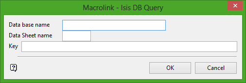
Database name
Enter the full name of the database, that is <proj><SDI>.dgd for design databases and <proj><odi>.<dsn> for non-design databases. The file extension suffix is not required.
Data Sheet name
Enter the name of the design (datasheet) for the database.
Key
Enter a string which will be used to match a key field in the database. Key fields are usually drill hole names, or sample numbers. For example, in the case of drill hole names, a hole name, such as DH054, would be used. All database records that have the matching key will be reported. The key can be a maximum of 40 alphanumeric characters.
Click OK.
When the Inquire option is used, the records matching the key are displayed in the Report Window.
The Macro/Command panel is redisplayed, with your command appearing in the bottom half. Refer to Macro/Command list for information on managing your commands.
Walk
Use this option to "walk" along a specified path (string). The string that you are going to use as the path must exist prior to starting this option. It also must have a unique name.
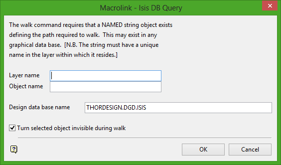
Layer Name
Enter the layer name that contains the string object which defines the path to walk.
Object Name
Enter the name of the object which defines the path to walk.
Design database name
Enter the name of the design database in which the above layer resides. The default is the current design database.
Base names can be used in all of the above names.
Turn selected object invisible during walk
Select this check box to turn the object invisible during the walk.
Click OK.
The Macro/Command panel is redisplayed, with your command appearing in the bottom half. Refer to Macro/Command list for information on managing your commands.
Visibility
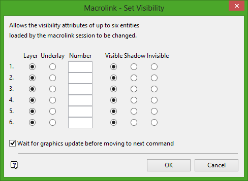
Use this panel to choose which layers or underlays (up to six) loaded by the current macro are visible, shadowed or invisible.
Layer
Select this option to change the visibility of a layer.
Underlay
Select this option to change the visibility of an underlay.
Number
Enter the number of the layer or underlay whose visibility you want to change. Layer and Underlay numbers are obtained from the Macro/Command Link panel. The numbers are located on the far right hand side of the panel, corresponding with the loaded layer or underlay. The numbers are defined as :U01, :U02, :L01, :L02, for Underlay 1, Underlay 2, Layer 1, Layer 2, in order of loading. Pictures are also loaded as underlays.
Visible
Select this option to make the layer/underlay visible.
Shadow
Select this option to make the layer/underlay shadowed.
Invisible
Select this option to make the layer/underlay invisible.
Wait for graphics to update before moving to next command
Select this check box to wait for the graphics to update before continuing on to the next command.
Click OK.
The Macro/Command panel is redisplayed, with your command appearing in the bottom half. Refer to Macro/Command list for information on managing your commands.
Wait
Use the Wait command to dictate the flow of the commands in a macrolink.
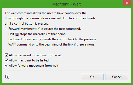
Allow backward movement from wait
Select this check box to send the control back to the previous wait command or to the beginning of the macro if there is none (using the < key).
Allow macrolink to be halted
Select this check box to stop the macro at that point (using the [ ] keys).
Allow forward movement from wait
Select this check box to execute the next command in the macro (using the > key).
Click OK.
The Macro/Command panel is redisplayed, with your command appearing in the bottom half. Refer to Macro/Command list for information on managing your commands.
Step On
A radio button labelled Step On is added to the Command list.
When using the Inquire option, a graphical navigation box is displayed. Use the arrow buttons on the this box, to move through each step of the macro at your own pace, or stop the macro at any given point. The heading of the box also tells you at which step of the macro you are located.
Step Off
A radio button labelled Step Off is added to the Command list.
Step_Off should be activated some time after the Step_On option. It removes the ability to step through the macro at your own pace, and returns the macro to automatic.
Clear
A radio button labelled Clear is added to the Command list.
When using the Inquire option, any object that was displayed using the macro is removed from the screen.
Macro/Command List
Once a command has been created, you are returned to the Macro/Command list panel and the command is added to the panel. Extra buttons are also added to the panel to allow you to edit, execute and delete existing commands and to insert new commands. Select OK on this panel to create the macro.
Insert Before
Select this option to insert a new command before the selected command.
Insert After
Select this option to insert a new command after the selected command.
Delete
Select this option to delete the selected command.
Edit
Select this option to edit the selected command. You will be allowed to edit all of the details for the selected command.
Execute
Select this option to execute the selected command.
Click OK.
