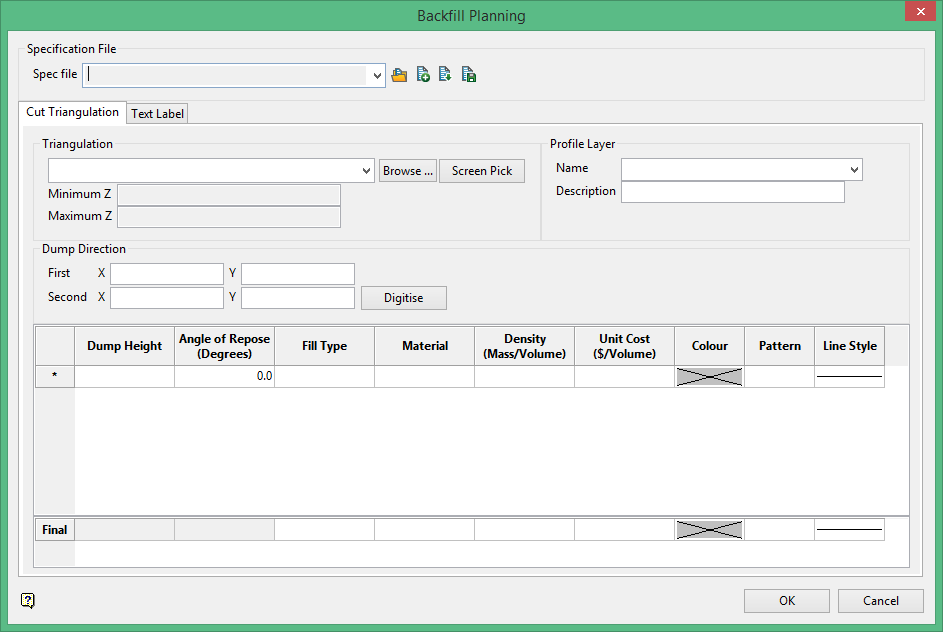
Backfill Planning
Takes in a triangulation and a segment to define a plane. The option outputs new triangulations that are cut from the cut planes defined in the panel from a height and a angle and design polylines that are profiled based on the segment plane.
On the Underground menu, point to Stope Design, then click Backfill Planning to display the following interface.
Specification file
-
-
 Search
 -
 New
New -
 Save as
 -
 Save
Save
-
Select a specification file from the drop-down, or click on the New icon to display the following panel.
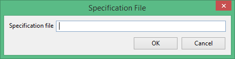
Enter the name of a new specification file, then click OK.
Triangulation
Select the triangulation from the drop-down list, browse for it, or select it from the screen. Once it has been selected, the minimum and maximum Z values will be automatically populated.
Profile Layer
The resulting cut planes are saved to a layer. Select a name for the layer and enter it here. A description is also helpful, however, it is not required.
Dump Direction
The dump direction refers to the direction from which material will be dumped from into the stope cavity. Click the  button, then draw where you want to see the cross-section to be generated through the triangulation. The First X and Y will indicate the starting location and the Second X and Y will indicate the ending location of your line.
Note: The starting location works closely with dump height, so thought should be taken concerning where the start of the line will begin.
Dump Height
The Dump Height is the height above the starting elevation from which the angle of repose will be drawn from. When you draw the line that represents the cut plane, the starting point will be the point directly above the point where the dump height will be measured.
Angle of Repose
Enter the angle of repose for the material used to fill the stope.
Material Properties
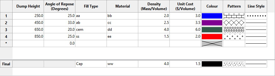
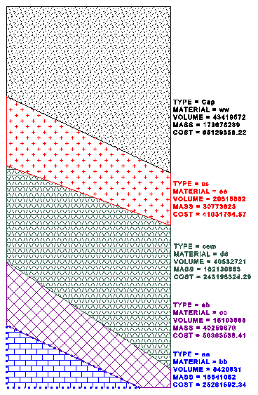
Enter the material properties such as fill type, material, density and unit cost. Vulcan will calculate a volumetric cost analysis bases on these numbers and provide an on-screen key showing the results.
Format
Select the colour, texture pattern and line style for each material. You may enter as many materials as you wish.
Final
When you have enter all the materials in the table above, there will be one last layer. For this final layer, select the colour, texture pattern and line style just like you did for the other layers. There will be no need to enter a dump height or angle of repose since this is the cap layer.
Example:
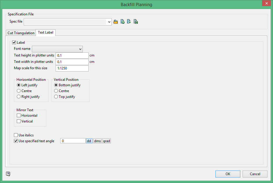
Text Label
Font
Select the font for 3D text. Due to the nature of the 3D text, only transformable (vector) fonts can be selected.
Text Height in plotter units
Enter the height, in plotter units, for the text.
Text Width in plotter units
Enter the width, in plotter units, for the text.
Unlike 2D text, 3D text can be stretched horizontally and vertically by varying the ratio of the height to the width.
Map Scale for this size
Enter the scale, as a ratio, used by the text height.
For example : If the text height is 0.1 (10cm) and the map scale is 1:1250, then the text will appear on the screen the same size as an object that is 125 units tall.
Horizontal Position
Select the horizontal positioning of the text, which can be left, centre or right justified.
Vertical Position
Select the vertical positioning of the text, which can be bottom, centre or top justified.
Mirror Text
Check one of these boxes to mirror the text horizontally or vertically.
Use Italics
Select this check box if you want the text to be in italics.
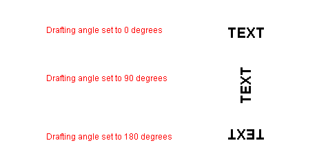
Use specified text angle
Select this check box if you want the text to appear at a specific angle.
For example: To enter a drafting angle of 50°, select the ![]() button and enter
button and enter 50 as the drafting angle.
Note: Simply select a different angle format button to convert a value, for example 50° will become 55.555556 if the ![]() button is selected.
button is selected.
Figure 1: Drafting angle examples