Annotate String
Use this option to annotate string objects, such as contour lines.
Note: The string objects must have been created as design strings rather than underlays.
Instructions
On the Model menu, point to Contouring, then click Annotate String.
Follow these steps:
-
Load the layer containing the strings onto the screen.
-
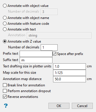
Select the type of labels to use for the annotations.
-
Annotate with object value - This will capture the object's value and use it as a label. Enter the Number of decimals for the annotation. The maximum number of decimal places allowed in a single label is 6. The default number of decimal places is derived from the Miscellaneous section of the Tools > Preferences option.
-
Annotate with object name - This will capture the object's name and use it as a label.
-
Annotate with feature code - If the strings were produced as part of a contouring procedure, then the major contours will be in a feature called "
CONTMAJ" and the minor contours in "CONTMIN". Contours of the same level are in one group, named "CONTOUR<n>" where<n>is the level. Hence you can choose to select the strings by feature and annotate all of the major and minor contours or select by group and annotate all contours at one level. -
Annotate with Z value - This will capture the object's elevation (Z value) and use it as a label. Enter the Number of decimals for the annotation. The maximum number of decimal places allowed in a single label is 6. The default number of decimal places can be set with the Preferences > Miscellaneous option.
-
-
Enter optional suffix and/or prefix text. The maximum size is 10 alphanumeric characters.
Select Space after prefix to insert a space between the prefix and the annotation.
-
Enter the Text drafting size in plotter units. Annotations lie in a straight line, that is, the text does not curve. The font used for the annotations is set through the Preferences > Defaults : 2D Text option.
-
Enter the Map scale for this size for the text size. This value along with the drafting size will determine the size of the text on the screen.
Example: If the text size is set to '0.10' (10 cm), and the drafting scale to '1:1250', then the text will appear on the screen the same size as an object that is 125 units long. Changing the scale, through either this option or the File > Plot > Plot All option to '1:1000' will result in the text appearing the same size as an object that is 100 units long. Changing the scale to '1:1' 000' results in a text size of 1000 and so forth.
Note: Fixed fonts appear on the screen the same size regardless of the map scale.
-
Enter the Annotation map distance, the distance between the annotations on the string. This value, along with the map scale, will determine the placement of the annotations on the screen.
-
Select Break line for annotation to annotate in the line. If this check box is not checked, then the annotations will appear above the line.
-
Select Perform annotation dropout to filter the annotation labels when the contour lines are spaced closely together.
-
Select Reverse annotations if the strings have been digitised anticlockwise. This will ensure that the annotations are printed the right way up. If this check box is not checked, and the strings were digitised anticlockwise, then the annotations will appear upside down.
Click OK.
The annotation labels of the selected objects are then displayed at the nominated distance.
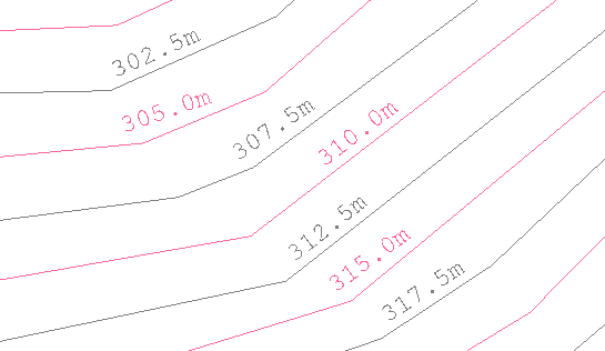
Figure 1: Annotating with Z values
Note: Use Design > Object Edit > Delete to remove the annotations.
