Creating a Project File (dg1)
Before Vulcan can be started for the first time, you must set up a project/job specification file (.dg1) containing startup parameters, such as the grid coordinates of your work area. The project file is used whenever you start a Vulcan session in that area, i.e. a project file must exist for each work area.
There are two methods of creating project files (.dg1), the first method is to create a simplified file, by using the VULCAN 3D Project Setup Wizard, which can then be edited once Vulcan is running. The second method involves starting the Workbench, with or without Vulcan running, and then using the New design parameters option in the Vulcan Explorer application.
Using the VULCAN 3D Project Setup Wizard
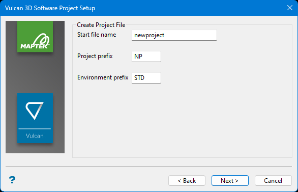
When you start Vulcan you will be prompted to select an existing project file or, if desired, to create a new file through the VULCAN 3D Software Project Setup Wizard. If you choose to create a new project file, then the following panel displays.
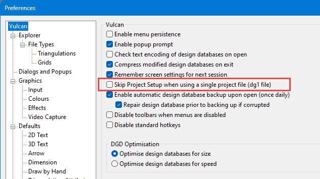
The VULCAN 3D Software Project Setup panel won't be displayed if you have enabled Preferences > Vulcan > Skip Project Setup when using a single project file (dg1 file) preference and your current working directory only contains a single project file.
Follow these steps:
-
Enter the Start file name and the Project prefix.
The project prefix is used in some naming conventions to organise or group files. Some options will automatically prefix the project code when generating file names. For example, design databases are constructed from the project code, followed by an option database identifier
<odi>. This project code must then be supplied with the<odi>when subsequently referencing the file. The maximum size of the project prefix is 4 alphanumeric characters. -
Enter the Environment prefix. The Environment prefix can have a maximum size of 4 alphanumeric characters. It is used when referring to the structure of Isis databases. These databases require additional information to define the way in which the data are stored internally. This information is found in the
<env>dd.ilbfile, which must be present in order for the database to be accessed.By convention, the project and environment codes should not be the same. For convenience, the project code, along with the environment code, are written into the
vulcan.chk -
Click Next. The following panel is then displayed.
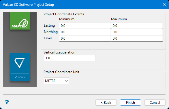
This panel allows you to set the coordinate extents, exaggeration, and units of length.
-
Enter the Minimum and Maximum for the Easting, Northing, and Level.
NoteTo create a project with unlimited extents, enter 0 (zero) for the minimum and maximum for all three parameters.
For 2D work, the Level coordinates may be set to 0 (zero).
-
Enter the Vertical Exaggeration. This value is the multiplying factor that is to be applied along the Z axis.
-
Select the Project Coordinate Unit used for the mapping window.
Editing the parameters of a project file
A project file (.dg1) can be created or edited using the Design Parameters Editor .
To edit a . file, open the Specifications folder in the Vulcan Explorer, click Design Parameters, then right-click on the file you want to edit. dg1
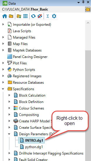
The Design Parameters Editor displays.
Follow these steps:
-
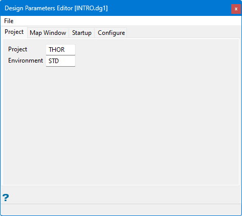
On the Project tab, verify that the Project and Environment settings are correct.
The Project is the same as the Project prefix mentioned above, and is used in some naming conventions to organise or group files. Some options will automatically prefix the project code when generating file names. For example, design databases are constructed from the project code, followed by an option database identifier
<odi>. This project code must then be supplied with the<odi>when subsequently referencing the file. The maximum size of the project prefix is 4 alphanumeric characters.The Environment is the same as the Environment prefix mentioned above. The Environment prefix can have a maximum size of 4 alphanumeric characters. It is used when referring to the structure of Isis databases. These databases require additional information to define the way in which the data are stored internally. This information is found in the
<env>dd.ilbfile, which must be present in order for the database to be accessed.By convention, the project and environment codes should not be the same. For convenience, the project code, along with the environment code, are written into the
vulcan.chk -
On the Map Window tab, specify the geographic coordinates of the window in which you want to work.
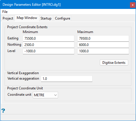
This panel allows you to set the coordinate extents, exaggeration, and units of length.
-
Enter the Minimum and Maximum for the Easting, Northing, and Level.
NoteTo create a project with unlimited extents, enter 0 (zero) for the minimum and maximum for all three parameters.
For 2D work, the Level coordinates may be set to 0 (zero).
-
Enter the Vertical Exaggeration. This value is the multiplying factor that is to be applied along the Z axis.
-
Select the Project Coordinate Unit used for the mapping window.
-
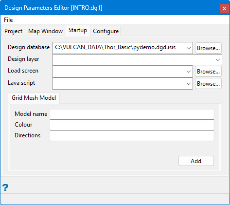
One the Startup tab, set optional startup defaults, such as the layer or grid model that you want loaded automatically when you start a session.
Note: All of the fields on this tab are optional.
-
Select the Design database. The drop-down list contains all design databases found in your current working directory. The design database will be opened at the same time that Vulcan is started.
If the nominated database does not actually exist, then a new database will be created. If this field is left blank, then you will be prompted to open a design database once Vulcan is started.
-
Specify the name of the Design layer that will be automatically opened and loaded when Vulcan is started. The available drop-down list contains the names of all layers found in the selected design database.
Note: This field cannot be used to create new layers. Only existing layers will be loaded and opened when Vulcan is started.
-
Select the Load screen. This is the name of the screen file (
.dg_spec) that will be automatically loaded when Vulcan is started. The drop-down list displays alldg_spec -
Select the Lava script. This is the name of the script that will be automatically loaded when Vulcan is started. The available drop-down list contains all lava script files found in your current working directory. Click Browse to select a file from another location.
-
Enter a grid mesh Model name. The model (
<gfi>) plus the model variable name (<mv>) will load the grid mesh model at the same time as Vulcan is started. -
Enter the Colour number. This is the index number of the colour in which the model is to be displayed. The currently available colours can be viewed and changed through the Colour button in the Status toolbar.
-
Enter the Directions for the grid lines. Valid entries are X, Y or B (Both).
-
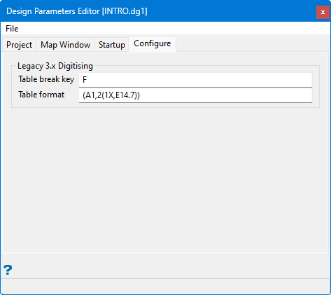
The Configure tab is provided for backwards compatibility. Vulcan 9 does not support non-Wintab compliant digitisers.
-
Enter a Table break key. This is the key that is most convenient to be used as the break or interrupt key on digitisers. The Table Break Key does not apply to WinTab digitisers.
-
Enter the Table format. This refers to the Fortran format statement that allows the program to translate data sent from the digitiser. The table format does not apply to WinTab digitisers. Vulcan expects a 1 (one) character push button code and 2 (two) real numbers representing the X,Y coordinates. This information must be entered in a Fortran format statement enclosed in brackets.
-
Select the Save option from File menu located in the upper left of the panel when you have finished entering the parameters. The format of the file name will be
<project_name>.dg1.
