Edit Structures
Assign Symbols to Geotechnical Structures
The Edit Structures option to assign symbols to geotechnical structures, as well as create and edit custom symbols. All symbol assignments will be saved in a <project code>.gtd file. The .gtd file will be stored in your current working directory.
Instructions
- Select Geotech menu
- Select Utilities submenu
- Select Edit Structures option
The following panel displays.
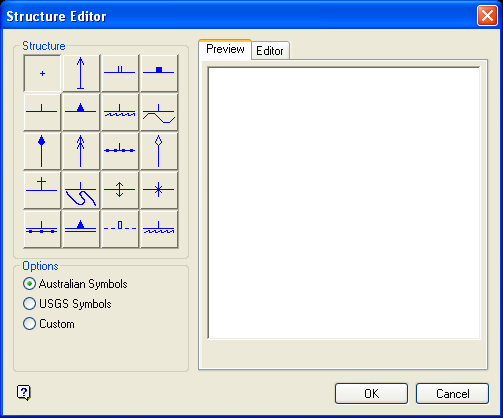
Structure Editor panel
Structure
This section contains a collection of predefined Geotechnical symbols. The units defined in your project specification file (.dg1), i.e. metric or imperial, will dictate which symbols are displayed through the Structures section i.e. Australian or USGS. No matter the default, either set of symbols will be available for use.
| Australian Symbols | |||
|---|---|---|---|
|
|
|
|
|
|
|
|
|
|
|
|
|
|
|
|
|
|
|
|
|
|
|
|
|
| USGS Symbols | |||
|
|
|
|
|
|
|
|
|
|
|
|
|
|
|
|
|
|
|
|
|
|
|
|
|


Options
This section allows you to indicate whether to use an Australian, USGS or custom symbol when displaying a particular geotechnical structure.
Editor
This section of the Structure Editor panel consists of the following tabbed panels:
Preview
Editor
Preview tab
The Preview tab allows you to view a selected symbol.
Editor tab
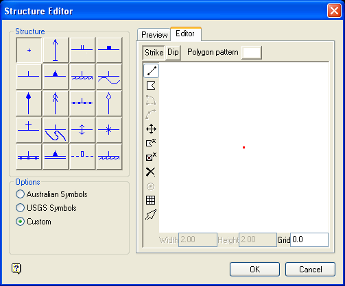
The Editor tab allows you to create new symbols and, if applicable, customise the default symbols. Press the Restore button to undo the customisations that have been made to a default symbol.
| Icon | Name | Description |
|---|---|---|
| n.a | Polygon Pattern | Allows you to apply a fill pattern to the polygonal objects in the selected symbol. |

|
Draw line |
Allows you to create a line. Steps:
|

|
Draw polygon |
Allows you to create a polygon. Steps:
|

|
Move point |
Allows you to move a point to a new position. Steps:
|

|
Delete object |
Allows you to delete an object. Steps:
|

|
Delete point |
Allows you to remove individual points from an object. Steps:
|

|
Delete all |
Allows you to delete all objects displayed in the Editor window. Steps:
|

|
Toggle grid | Allows you to toggle grid display, i.e. show or hide. |
|
|
Select object | Allows you to select objects from in the Editor window. This button needs to be selected prior to using the editing tools, i.e. the Move point, Delete object, Delete point and Delete all icons. |
| n.a. | Grid | Enter the size for the grid squares. |
Only line and polygon objects are honoured in the Structure Editor panel. Objects, such as arcs, are not supported.
Select OK.
The symbol assignments will be saved in your .gtd file.
