Block Model Variogram
Use the Block Model Variogram option to generate up to five variograms at the same time using one or more block model variables.
Instructions
On the Block menu, point to Variography, then click Block Model Variogram.
Note: If a block model is not currently open, you will be prompted to open one first.
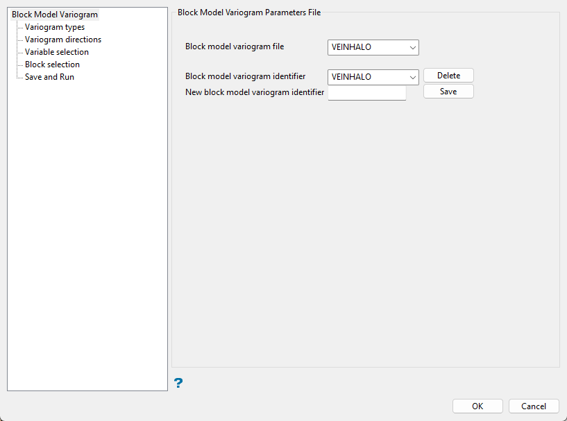
This section allows you to define, copy and delete the Block Model Variogram specification file (.var) and parameter identifiers.
Follow these steps:
-
Enter, or select the Block model variogram file from the drop-down list, the name of the Block Model Variogram specification file (
.var) that you want to open. The drop-down list contains all of the.varfiles found in the current working directory. To create a new specification file, enter the name of the new file. -
Enter, or select the Block model variogram identifier from the drop-down list, the name of the block model variogram parameters identifier that you want to open. The drop-down list contains all of the identifiers found in the nominated Block Model Variogram specification file.
-
Enter the name of the New block model variogram identifier that you want to create.
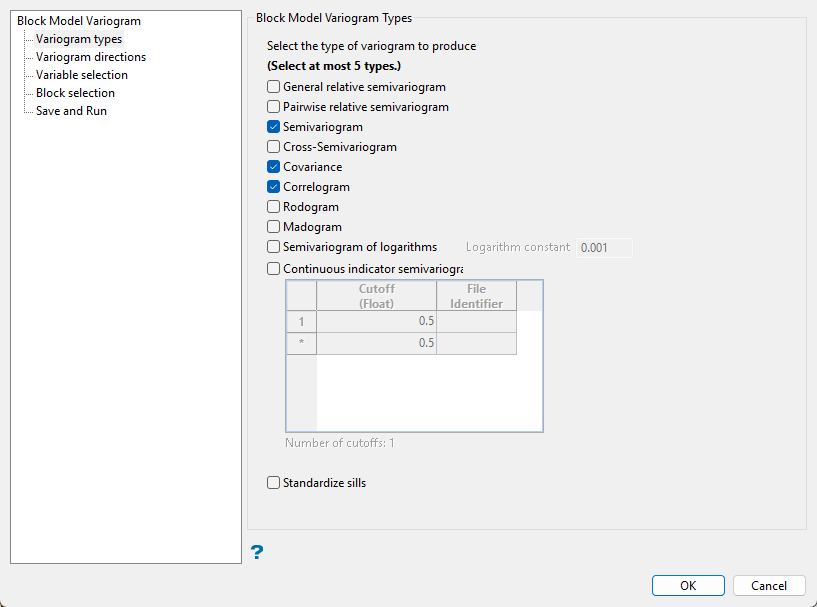
Variogram types
Follow these steps:
-
Select up to 5 variogram types to create.
-
Enable Standardise sill if you want to standardise the variogram sill by dividing the results by the sample variance. This is useful when calculating a semivariogram because instead of reaching the sill at the sample variance it will reach it at 1.
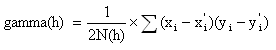
This is like the standard semi variogram, but divided by the mean of the data values.
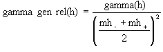
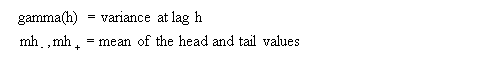
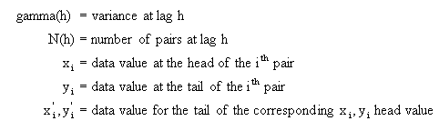
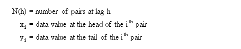
where:
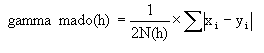
This is like the standard semi variogram, but each difference is divided by the mean of the sample values.
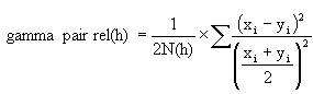
where:
This is the standard semi variogram.
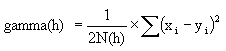
where:
where:
![]()
where:
where:
![]()
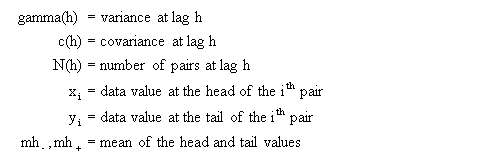
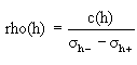
where:
where:
![]()
where:
Transform data as 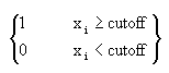 and compute the semivariogram.
where:

Variogram directions
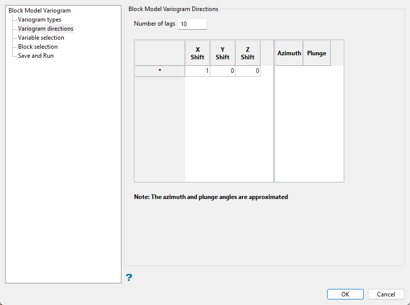
This section allows you to define the direction in which to calculate the experimental variograms, as well as the number of lags.
Follow these steps:
-
Enter the Number of lags or bins to be computed. The greater the number of lags, the larger the distance at which variography is computed. In most cases, it is unnecessary to compute lags at very large distances.
-
As the X/Y/Z Shift data is regularly spaced, directions are defined by the number of blocks that must be shifted in each direction.
X Shift Y Shift Z Shift Direction 1 0 0 Bearing 90°, plunge 0° 0 1 0 Bearing 0°, plunge 0° 1 1 0 Bearing 45°, plunge 0° 1 1 -1 Bearing 45°, plunge -45° Note: The Azimuth and Plunge are the approximate representation of the direction defined by the X, Y and Z shifting.
Variable selection
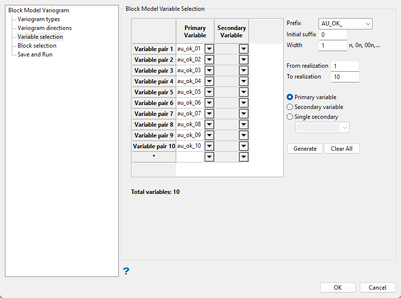
This section allows you to select the block model variables that will be used to calculate the variograms. The primary variable will be used to calculate the variograms, while the secondary variable is used to calculate cross variography.
Follow these steps:
-
Enter the Prefix for the variable name. You can use one from the drop-down list or enter your own.
-
Enter the starting number in the sequence in the Initial suffix field.
-
Enter the minimum number of characters that can be used to represent a number in the Width field.
Example: A prefix of
simwith an initial suffix of 1 and a width of 3 would result insim001as the first simulation field. -
Specify an initial and final realisation in the From realisation and To realization fields. These values are only used to calculate the number of realisations.
-
Indicate which column you are creating the naming conventions for, Primary variable, Secondary variable, or Single secondary.
Primary variable - This column defines the list of block model variables that will be used to calculate the variograms.
Secondary variable - This column defines the list of block model variables that will be used as a secondary variable when calculating cross variography, as well as when each primary variable is calculated with a different secondary variable.
Single secondary - Select this to option to use a single secondary variable for cross variography. The chosen variable will be used for each primary variable. The variable can be selected from the drop-down list.
-
Use the Generate button to populate the field list. .
Click the Clear All button to remove all entries and delete the current lists.
Block selection
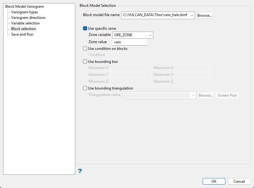
Use this panel to set up various block selection options. Select any of the options to limit the blocks used.
Select this checkbox to limit the estimation to those blocks where a specified variable equals a certain value. Both the variable and the value are forced to be lowercase.
Select this checkbox if you only want to apply a condition to the blocks to be estimated. A single condition can contain up to 132 alphanumeric characters. Refer to Appendix B of the Vulcan Core documentation for a list of available operators/functions.
Select this checkbox to restrict the estimation to those blocks whose centroids lie within a specified range of co-ordinates. Enter the minimum and maximum co-ordinates (in the X,Y and Z directions). These co-ordinates are offsets from the origin of the block model (that is, block model co-ordinates).
Select this checkbox to limit the estimation to those blocks that lie within a specific solid triangulation. The triangulation name can either be manually entered or selected from the drop-down list. Click Browse to select a file from another location. You can also select loaded triangulations from the screen by clicking the Pick Screen option.
Click Save and Run you to save and run the defined parameters
