ICF Tables Setup
Use this option to configure translation/conversion tables that will use an ICF table to translate patterns, colours, symbols, font, and layer names.
The tables will handle pattern, colour, line type, and font style conversions automatically for both file imports and exports. Layer name translations will be performed upon request. Symbol translations for export will also be handled automatically, whereas symbol translations for import are performed upon request.
If no ICF tables are set up, the exported data will be without pattern, colour, font style, line type, or symbol information. Imported data will be loaded with the currently selected colour, line type, and default font. Blocks imported as DGD symbols will show the symbol that matches the block name. If there is no such symbol, then a point marker (+) displays.
Instructions
On the File menu, click Import or Export, then click AutoCAD (dwg, dxf, dxb) in the File Format column on the left side of the panel, and select ICF Tables Setup for the File Type on the right.
Click OK to display the panel used to configure ICF tables.
Pattern Conversion
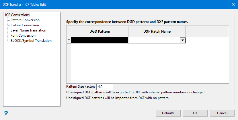
Pattern Size Factor
Enter a size factor for the pattern hatching. A factor of 4 will be used automatically if no edits are made. A maximum of 50 can be used.
Colour Conversion
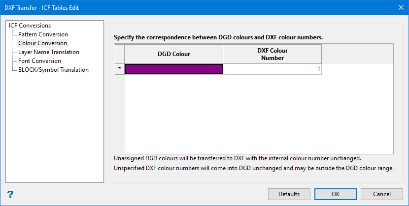
Use this tab to correlate the colour table used in Vulcan with the appropriate colour numbers, from 0 - 999, in the external graphics system.
Imported data with undefined colour numbers will use the default Vulcan colour. The default colour is set through the Status toolbar. The export data without colour information, set the colour numbers to '0'.
When you click in a cell in the DGD Colour column, the current colour table displays.
Select the required colour and then enter a colour number in the DXF Colour Number column. Refer to the AutoCAD Colour Index section for the appropriate AutoCAD colour numbers.
Layer Name Translation
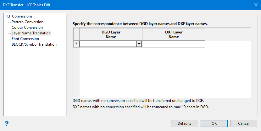
Use this tab to correlate layers regularly used in Vulcan with similar layers in the external graphics system.
Translations for up to 32 layers in Vulcan may be defined. The maximum size for the DXF layer name is forty alphanumeric characters. The layer name translations are only used if the appropriate option is chosen when importing or exporting.
Select the layer name from the drop-down list (all layers in the design database are contained in the list) in the DGD Layer Name column and enter the name of the DXF layer in the DXF layer column.
Font Conversion
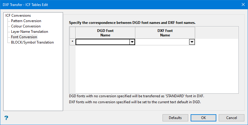
Use this tab to correlate the various fonts available in Vulcan with an appropriate font type in the external graphics system.
Translations for up to 12 font styles in Vulcan may be defined. The Vulcan fonts are selected from the drop-down list. The corresponding external font may also be selected from the drop-down list or entered manually (of the 23 standard fonts available in AutoCAD, 9 are displayed in the list - any others must be manually entered). The matches are as follows:
|
Vulcan |
AutoCAD |
|
scaled |
standard |
|
scaled |
monotxt |
|
futura light |
Romans |
|
times italic |
italics |
|
script |
scripts |
|
Greek |
Greeks |
|
gothic English |
gothice |
|
gothic German |
gothicg |
|
gothic Italian |
gothici |
Imported data without font information will use the default Vulcan font. The default font is defined through the Defaults > 2D Text section of the Tools > Preferences option.
Exported data without font information will use the standard font.
BLOCK/Symbol Translation
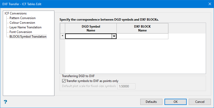
Use this tab to correlate DXF block with a Vulcan symbol. Translations for up to 20 DXF blocks may be defined.
Imported blocks for which no Vulcan symbol is defined, will be shown with a point marker (+).
Select the Vulcan symbol from the drop-down list, an enter the name of the DXF block in the DXF Block Name column.
Within Vulcan, symbols are stored in a separate design database: symbols.dgd.isis in the ENVIS_RESO area.
If this design database exists, then you may choose to transfer symbols either as single points to be referenced by appropriate blocks in the external system or as fully constructed designs taken from the design database. In the latter case, fixed-sized symbols are drawn according to the scale defined in this panel. Centre-scaled symbols are drawn with coordinates matching those seen on the screen display.
Transferring DGD to DXF
If the symbols database cannot be found when exporting, then only the symbol origin points are transferred. This does not apply when importing as symbols do not exist in AutoCAD.
Click OK.
The conversion table <proj><dxf>.icf is then created.
