Axes
Display Axes/Grid over a Section
The Axes option to place a temporary grid or set of axes in the current Section view.
Note: This option can only be used when in Section View.
Instructions
- Select Geotech menu
- Select Section submenu
- Select Axes option
The following panel displays.
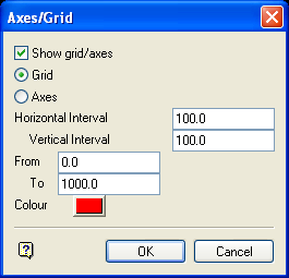
Axes/Grid panel
Show grid/axes
Select this check box to display a grid or axes. If unticked, then the grid/axes will be switched off (if currently displayed).
Grid
Select this option to display a grid. Like a coordinate grid in a 3D window, the grid is an underlay that cannot be edited and its labels cannot be printed. A grid is removed using the Analyse > Grid > Remove option.
Axes
Select this option to display two annotated axes. The annotations are text objects, and as such can be edited and printed. The axes are deleted on return to Plan view.
Horizontal/Vertical Interval
This controls the interval of the check marks and labels along the horizontal and vertical axes.
Tip: The side of the horizontal axis should be set to a value just greater than the length of the section line.
From
Sets the height of the grid.
To
Sets the height of the top of the grid, and the maximum height to which the vertical axis extends.
Colour
Select the colour in which the grid or axes displays. The colour is selected from the current colour table.
Select OK.
The annotated grid or axes are then displayed. To return to Plan view, use the Plan View option.
