Panel Caving Designer
Use this to design drifts and crosscuts in a fast and interactive way for a production-level mine using the panel caving method.
Instructions
On the Underground menu, point to Panel Caving Designer, then click New Project.
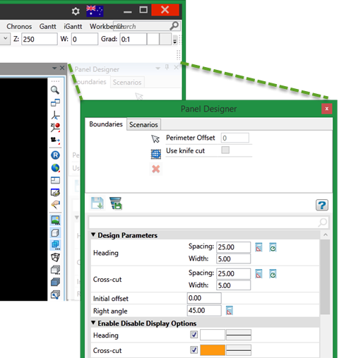
Undocking the Panel Designer controls
If it is more convenient, the Panel Designer parameter controls can be undocked from the Workbench, then resized and moved anywhere on your screen.
Design Parameters
Heading Spacing
Change the distance between headings.
Heading Width
Change the width of headings.
Cross-cut Spacing
Change the distance between cross-cuts.
Cross-cut Width
Change the width of cross-cuts.
Initial offset
Distance from the reference point to the first point of the heading.
Right angle
Angle between the cross-cut and the heading.
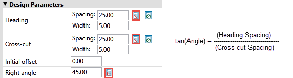
Calculate Buttons
To use the Calculate buttons, highlight the parameter that you want to calculate, then click the button next to it to complete the calculation.
Method 1. Calculate parameters starting from any two of the Heading Spacing, Cross-cut Spacing, or Angle fields. The highlighted field will be calculated automatically.
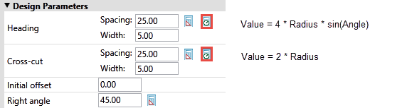
Method 2. Calculate parameters starting from the Ellipsoid radius and Angle fields. The Heading Spacing and Cross-Cut Spacing fields will be calculated automatically.
Enable Disable Display Options
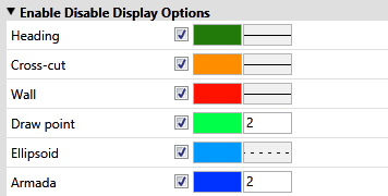
Use the checkboxes to select which features are visible or hidden.
Select the colour of each feature by clicking on the colour tab.
Select the line style or point thickness by clicking on the style tab.
Layout
The layout section is used to orient the panel.
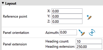
Reference point
Enter the X, Y, and Z coordinates, or click the  Digitise button to use your mouse to select a reference point in the 3D workspace.
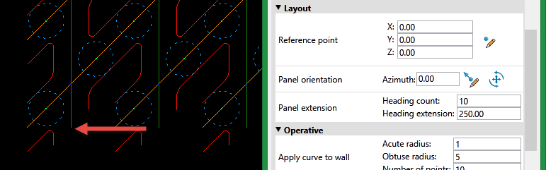
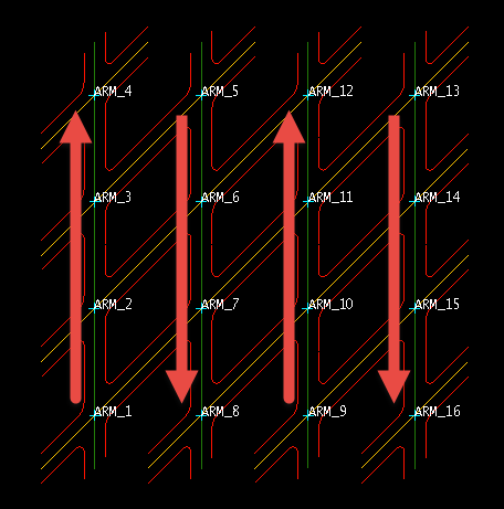
The reference point is at the start of the first heading located near the lower, left corner of the panel set. (See arrow in image above.)
Panel orientation

|
Select two points to calculate the azimuth. |

|
Orient the panel by clicking and dragging the circle. |
Panel extension
Heading count
This controls the number of headings in the panel.
Heading extension
This controls the number of cross-cuts. Set the extension of the heading. The number of cross-cuts is calculated by the following equation:

Operative
Apply curve to wall
Acute radius
Set the radius of curvature for the acute angle.
Obtuse radius
Set the radius of curvature of the obtuse angle.
Number of points
Set the number of points to use in the radius of curvature.
Draw point
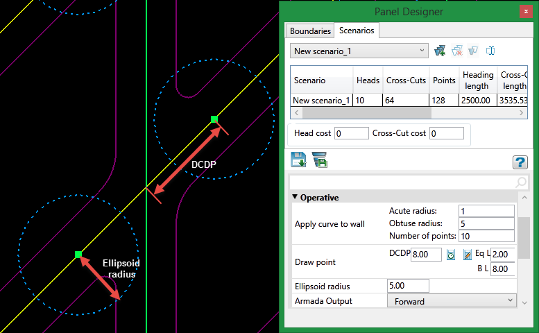
DCDP
Enter the distance to the centre from the draw point. (DCDP = Distance Centre to Draw Point)
Eq L
Enter in the Equipment Length.
B L
Enter in the Batter Length.
Ellipsoid radius
Enter the distance for the ellipsoid radius.
Armada Output
The armada is the intersection between the heading and the cross-cut. There are two ways to enumerate the intersections:
-
Forward, in which the armada in each heading is numbered from south to north
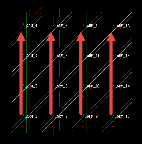
-
Forward and Back, in which the armada in each heading is numbered alternating from south to north or north to south.
Output preferences
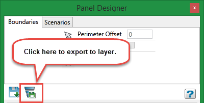
When the design is ready, you can export the objects out to a layer.
-
Enter a prefix name that will be attached to the start of the OBJECT NAME.
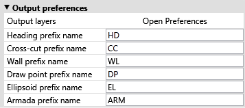
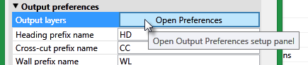
-
Click Open Preferences to display the Output Layer panel.
-
Use this panel to select which objects will be included in a layer. Each layer can have from 1 to 6 objects associated with it. It does not matter if another layer has a similar object since each layer is treated separately.
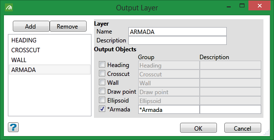
Add a new layer by clicking the Add button. Select the object by checking the box beside the name. -
When you have completed the selection of objects, click the Export Layer button to export them to layers.
Note: To label objects when viewing in Vulcan's 3D workspace, right-click on the object and select Label from the context menu, then select Object name.
Boundaries Tab
You can set a boundary in two ways:
1. Select the boundary polygon from the screen.
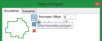
2. Import the boundary polygon from a CSV file.
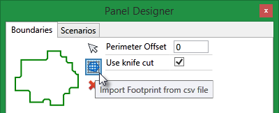
A panel will be displayed that will allow you to select the CSV file from the drop-down list, or browse for it by clicking the Browse button.
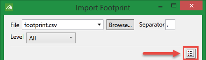
Click the toggle button to switch between a list view of available footprints and a detailed view.
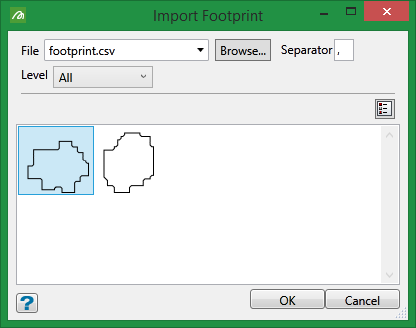
List view
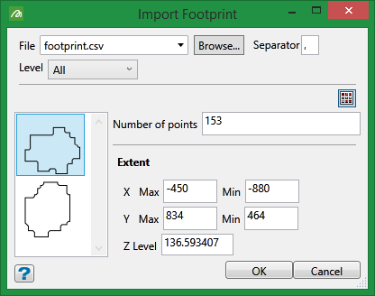
Detailed view
Highlight the boundary you want to use, then click OK to select the boundary, close the panel, and return to the main Panel Designer interface.
After you have selected a boundary it can be easily removed by clicking the Red X button.
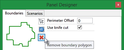
Perimeter Offset
Select the distance for the offset and press ENTER. The boundary polygon will be projected outward, with all headings projected to intersect with the projected boundary.
Use knife cut
Select this option to cut the panel design at the border of the boundary polygon.
Scenarios Tab
Use the drop-down list  to select the scenario.
All edits to the scenarios parameters will affect the scenario that has been selected in the drop-down list.

|
New Scenario |

|
Delete Scenario Warning!!! This will delete the scenario selected in the drop-down list, not the scenario that might be highlighted in the table. |

|
Duplicate Scenario |

|
Rename Scenario |
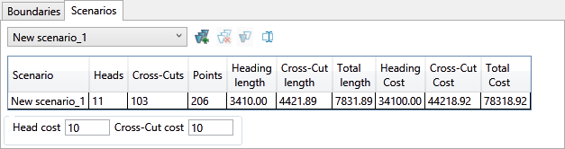
The table includes a summary for each scenario by showing the number of heads, cross-cuts, points, as well as heading and cross-cut length.
It also provides estimate for the heading and cross-cut costs based on your input into the Head cost and Cross-cut cost fields located just below the table. These inputs are multiplied by the length of each respective field.
The Total Cost is sum of the Heading Cost and Cross-cut Cost.
