Map Image to Drillhole
Map a Textured Image to a Triangulated Drillhole.
The Map Image to Drillhole option to map a textured image to a triangulated drillhole. A texture-mapped drillhole can be directly used to determine the location and orientation of discontinuities visible on the drillhole texture. This data can also be used through the Geotech menus to digitise geotechnical features in true 3D space.
Prerequisites:
- A geological database containing downhole survey data (DSR) and caliper data that defines where the hole goes.
- An image file, in either the JPEG (
.jpgor.jpeg) or tagged image file format (.tifor.tiff) that has been generated from the downhole instrument. Each row of pixels is assumed to represent a measurement taken from inside of hole, and perpendicular to the hole at that point. - Information about the image so it can be mapped to the correct part of the drillhole. This information consists of the following:
- Downhole depths of the top and bottom of the image. This information can be read from a Wellcad WAG file.
- Orientation of the vertical edge of the image.
![]() Note
Note
The Map Image to Drillhole option will create a triangulation of the drillhole that matches the section of drillhole covered by the image. Each time the DSR or caliper data changes; a 'ring' of triangle vertices will be created. You can set the number of triangle faces in each 'ring' based on the image resolution, or by entering it manually.
The Map Image to Drillhole option will also create a special Image Registration file (.ireg). This file, along with the associated triangulation and image, allows the image to be texture mapped to the triangulation.
Instructions
- Select Geotech menu
- Select Utilities submenu
- Select Map Image to Drillhole option
The Map Image to Drillhole panel displays. This panel is divided into four separate tab panels:
- Drillhole
- Caliper
- Image
- Options
Drillhole tab
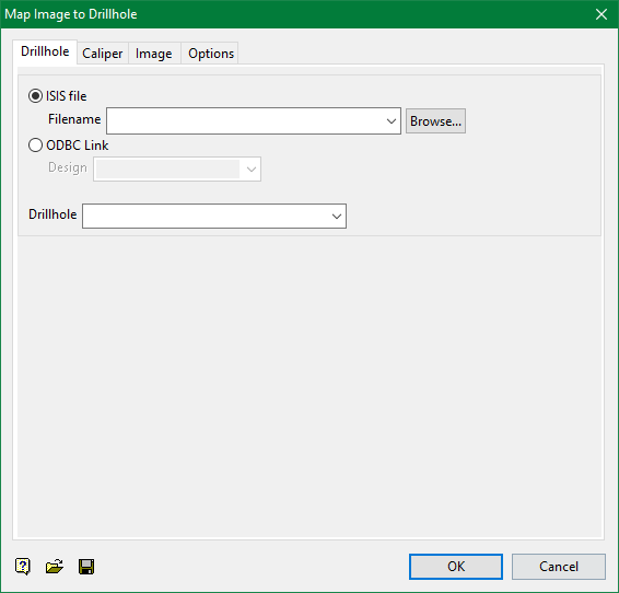
Drillhole
Select the drillhole to use.
Caliper tab
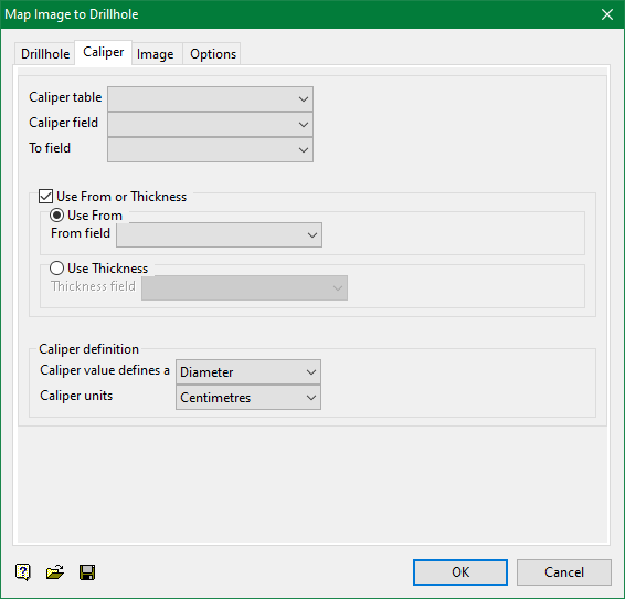
Specify the caliper table that contains the required downhole depth, as well as the field that contains the bottom depths.
Use From or Thickness
Select this check box to use a specific From or Thickness field. The required field can either be manually entered or selected from the appropriate drop-down list.
Caliper definition
This section allows you to define the caliper's units of measurement, and if the value defines the radius or diameter at the point perpendicular to the hole.
Image tab
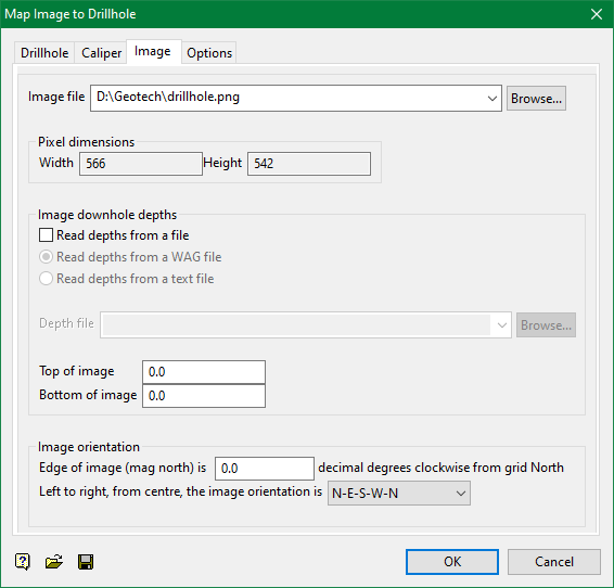
Image file
Select the image file that you want to map to the chosen drillhole. Once an image has been chosen, the Width and Height fields will be automatically populated with the appropriate pixel dimensions.
The drop-down list displays all image files (with the .jpg, .jpeg, .tif or .tiff extensions) found in your current working directory. Click Browse to select a file from another location.
Image downhole depths
Read depths from a file
Select this check box to read the downhole depths from a nominated file. You have the choice of either using an existing Wellcad WAG file (.wag) or a nominated text file (.imap_txt). If this checkbox is not ticked, then you will need to manually define the top and bottom values of the image in relation to the chosen drillhole. Ensure that the values are in the range of caliper data downhole depths.
Read depths from a WAG file
Select this option to read the downhole depths from a nominated Wellcad WAG file (.wag). When using this option, the drop-down list displays all .wag files found in the current working directory. Click Browse to select a file from another location.
Read depths from a text file
Select this option to read the downhole depths from a nominated text file (.imap_txt). When using this option, the drop-down list displays all .imap_txt files found in the current working directory. Click Browse to select a file from another location.
The .imap_txt file, which will be treated as a comma delimited database, should have the following file structure.
        <image name1>,<top depth1>,<bottom depth1>         ........         <image nameN>,<top depthN>,<bottom depthN>           Â
Image orientation
Edge of image (mag north) is
Enter the vertical edge of the image orientation.
Left to right, from centre, the image orientation is
Select from the drop-down list, the orientation of the image to be wrapped to the drillhole. Select N-E-S-W-N (Clockwise) if the image is orientated from North, to East, to South, to West and back to North, or select N-W-S-E-N (Anti-clockwise) if the image has been orientated in the reverse direction.
Options tab
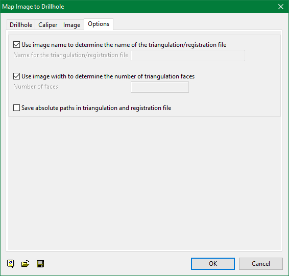
Use image name to determine the name of the triangulation/registration file
Select this check box to use the image's filename to determine the name of the resulting image registration file and it's associated triangulation. If this checkbox is not ticked, then you will need to specify the name of the resulting image registration file and it's associated triangulation.
Use image width to determine the number of triangulation faces
Select this check box to use the image width to determine the number of triangulation faces. If this checkbox is not ticked, then you will need to specify the number of triangulation faces.
Save absolute paths in triangulation and registration file
Select this check box if you only want to store the file names and not the full paths in the triangulation and image registration, allowing you to copy the image registration file and it's associated triangulation to another folder.
If you have chosen to use the image name to name the triangulation and image registration file, then only the base name (i.e. after removing the path and extension) will be used. The image registration file and the triangulation will always be created in the current working folder.
Select OK.
Note: The panel information can be saved and loaded from a specification file (.mpi.spec) using the save and load controls at the bottom left of the panel.
