Export Data to VRML Block Model
Use the Export Data to VRML option to export block models, design data, grids, and triangulations to a .wrz (comclicked) or.wrl (uncomclicked) file. Once exported, the resulting file can then be viewed with any VRML viewer, for example the Cortona3D Viewer. Additionally, using a VRML plug-in you can insert the file into a variety of applications such as Microsoft Word or PowerPoint.
The results from a VRML export offers greater image quality over the corresponding NGRAIN export option.
Instructions
On the File menu, click Export to display the Export panel.
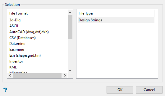
Click VRML in the File Format column on the left.
Select Block Models (Model) from the File Type field on the right side of the panel.
Click OK to display the Export to VRML panel.
Block model attributes
Block model attributes
Block model file name
Select the block model to export. Click Browse to select a file from another location.
Variable name
Select the grade variable to export. The drop-down list contains all of the grade variables defined in the nominated block model.
Colour scheme
Select the colour legend to be used to colour the chosen grade variable. The drop-down list contains all block colour legends found in your colour scheme file (.scd).
Block selection
Either all blocks or specific blocks can be selected. If you select Select specific blocks by, then you must enter one or more of the following selection criteria:
Variable
Select this check box to restrict the blocks by a block model variable. You will need to specify the variable, as well as a particular value.
To restrict blocks to those where Material equals Ore, select 'Material' as the variable (from the drop-down list) and enter 'Ore' as the value. However, if you require all blocks thatdo nothave this specified value, then enable the Reverse matching check box. The block model variable may be numeric (for example the grade variable 'Au') or character (for example 'Geology') variables.
Bounding triangulation
Select this check box to restrict the blocks by a triangulation. This is useful when, for example: you want to evaluate reserves in a particular solid triangulation such as a stope. You may also select the Use block centres check box and use it with this restriction.
This option does not apply to open or 2D triangulations.
Bounding box
Select this check box to restrict the blocks by a box. The bounding box is defined in Interactive or Coordinate mode. The required mode is selected from the Box Thickness panel, which displays once the Block Selection panel has been completed. You may also select the Use block centres check box and use it with this restriction.
Section thickness
Select this check box to restrict the blocks by a section plane. You will need to enter its associated thickness. The blocks that are in this thickness will be selected.
The section plane can be selected by line, points or grid coordinates. This information is entered through the Section Plane panel, which displays once the Block Selection panel has been completed. You may also select the Use block centres check box and use it with this restriction.
Condition
Select this check box to use a further constraint upon a numeric block model variable, for example Fe GT 10.0 (iron value greater than 10.0). The maximum size of the condition is 132 alphanumeric characters. A list of available operators/functions to use when defining this condition is provided in Appendix D.
Bounding surfaces
Select this check box to restrict the blocks by bounding surfaces. Once the Block Selection panel has been completed, you will be required to select (from the screen) the top and bottom surface triangulations. Only blocks that lie in the overlapping sections, as viewed in plan view, of the surfaces are selected. You may also select the Use block centres check box and use it with this restriction. This check box will be disabled when the Cut and fill surfaces check box is in use.
Cut and fill surfaces
Select this check box to restrict the blocks to those that fall in two intersecting surfaces. This check box will be disabled when the Bounding surfaces check box is selected.
The required triangulation surfaces are specified through the Cut and Fill Surfaces Selection panel, which displays once the Block Selection panel has been completed.
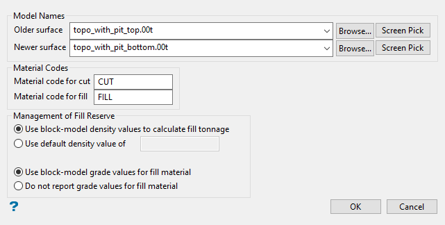
Cut and Fill Surfaces Selection panel
Model names
Older surface
Enter, or select from the drop-down list, the name of the old triangulation surface. Click Browse to select a file from another location.
Newer surface
Enter, or select from the drop-down list, the name of the newest triangulation surface. Click Browse to select a file from another location.
Material codes
Material code for cut / Material code for fill
Enter the material codes for the fill and cut.
Management of fill reserve
Use this section to define the conditions when calculating the tonnage and grades for the fill.
Use block-model density values to calculate fill tonnage
Select this option to use the density values from the chosen block model.
Use default density value of
Select this option to use a specific density value.
Use block-model grade values for fill material
Select this option to use the grades values from the chosen block model when calculating the grade values for the fill material.
Do not report grade values for fill material
Select this option if you don't want to calculate, or report on, the grade values for the fill material.
Click OK.
Reverse matching
Select this check box to select outside the specified regions. See the description of the Variable field. This check box will be disabled when the Cut and fill surfaces check box is in use.
This check box is only available when using the Advanced Reserves Editor, or when limiting the block selection by a bounding box, triangulation or surfaces.
Use block centres
Select this check box to use the full cell evaluation method. If this check box is not selected, then the proportional cell evaluation method will be used instead.
- Full cell evaluation: Include blocks if the block centroid is in the region. The entire block will be included.
- Proportional cell evaluation: Include those blocks that touch the region, and evaluate reserves according to the proportion of the block's volume that lies in the region. Proportional cell evaluation calculates and reports the exact proportion of a block in a solid triangulation. When selecting blocks, all blocks that touch the region are selected.
The Convert to VRML panel displays.
Select VRML file
Enter or select the file name to be used to store the exported data. The drop-down list contains all VRML (.wrz or .wr;) files found within your current working directory. Click Browse to select a file from another location. To create a new file, enter the file name and file extension.
Compressed
Select this option to export the VRML file in a compressed format. The resulting file will have a .wrz extension.
ASCII
Select this option to export the VRML file in an ASCII format. The resulting file will have a .wrl extension. This format is only recommended for users that want to work directly with the exported VRML file.
Click OK.
The export will continue and the resulting file will be stored in the current working directory.
Once the selected grid(s) have been successfully exported, the resulting file can then be viewed with any VRML viewer, for example the Cortona3D Viewer. Additionally, using a VRML plug-in you can insert the file into a variety of applications such as Microsoft Word or PowerPoint.
For design data exports that fall outside of the VRML viewing range (coordinates above/below +/- 32 million) the data will be shifted and/or shrunk as necessary to fit within the available space.
