Create
Set Up a Shaft Transformation Window
Use the Create option to create a shaft transformation window. This type of window provides a view of design data (and models) that gives a "flattened" view of the walls of an essentially cylindrical object. Shaft transformation windows are useful when designing inclined shafts, tunnels or drifts.
The windows are stored in the Windows Parameters file (<proj>.wnd).
Instructions
On the View menu, point to Shaft View, and then click Create to display the Shaft Window Create panel.
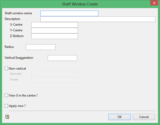
Shaft window name
Enter the name of the shaft view window (a maximum of 20 alphanumeric characters).
Description
Enter an optional 40 alphanumeric character description of the window.
X-Centre/Y-Centre
Enter the X and Y coordinates for the centre of the cylinder, for example, the shaft centre coordinates. This becomes the origin of the shaft window.
Z-bottom
Enter the Z coordinate for the base of the cylinder. As this value defines the base of the area, enter a value that will ensure that the shaft window covers the area of interest. The Z coordinate in an orthogonal 3D window is mapped to the Y coordinate in a shaft window.
Radius
Enter the nominal radius of the shaft or drift. It becomes the default Z value in the shaft window. For non-vertical shaft windows, this also defines the orthogonal Z coordinate of the origin.
Vertical Exaggeration
Enter the viewing aspect ratio for the shaft window. For example, to setup a window where the aspect ratio is approximately 1:1 (Y:X or metres:degrees), a vertical exaggeration of 360 divided by the circumference must be applied.
Non-Vertical
Select this check box only if the shaft window is non-vertical. Specify the azimuth and grade of the centre line of the cylinder. The grade may be entered in degrees, % or as a ratio.
View 0 in the centre
Select this check box to set the north point in the centre of the window. Thus the south point will form the left and right edges of the shaft window, that is, the window that is created displays degrees along the X axis from right to left as 180° to 0° to 180°. Don't check this box to set the south point in the centre of the window.
Note: For non-vertical shafts (tunnels) the roof is normally displayed in the centre. Selecting this check box displays the floor in the centre instead of the roof.
Apply now
Select this check box if you want this window to become the active window. If this check box is not selected, then the window will be saved, but not made active.
Click OK.
The shaft transformation window is then generated and saved. Refer to the Overview section for editing considerations.
