Create UG Drive
Use the Create UG Drive option to create cross sections and open ended solid representations of the underground drives, cross cuts, etc., by supplying a grade line, a set of chainage values, and a left, right, back (up) and floor (down) offset from each chainage point. In addition, each drive cross section may be given a bearing and gradient relative to the grade line.
Instructions
- Select Survey menu
- Select UG Survey submenu
- Select Create UG Drive option
The Create UG Drive panel displays. The panel has three tabs:
-
General parameters
-
Survey stations
-
Output
General parameters
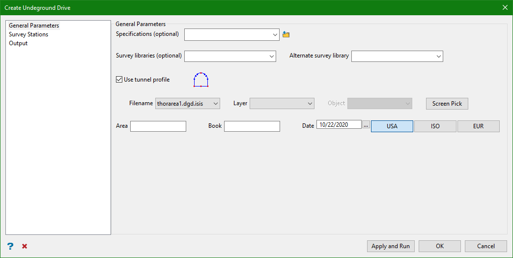
Specifications
This option allows the drive data to be loaded from a Vulcan UG Drive specification file (.ugd for old versions and .ugdv2 for the new system). You can choose one of the specification files from the drop-down list or browse to select from a different folder. Choosing a spec file is optional as you can manually enter data in the Survey stations.
Survey Libraries
Enter, or select from the drop-down list, the name of the station library that contains the data for the originating and terminating survey stations (used to define the grade line). Specifying a survey library is optional.
Alternate Survey Library
Enter, or select from the drop-down list, the name of an alternate station library that may have been used to store the originating or terminating stations. Specifying an alternate survey library is optional.
Use tunnel profile
This option works as a template for creating tunnel profile from the survey pick data. It is created as a design object in plan view.
Choose a design database file and load layers and objects from the drop-down list associated with that database or you can pick objects from the screen. If the profile is selected from the drop-down list, you can check the profile visually by loading the object.
Note: To avoid manual work, this option assumes that the XY plane of the profile is positioned arch up. The profile needs to be a flat closed polygon and none of the tunnel's survey lines can be vertical.
The left and right offsets are measured looking at the direction of survey line (eg. from originating to terminating station). The sum of left and right offsets defines the width of the profile. The position of origin defines the position of the vertical offsets within the profile. The sum of top and bottom offsets defines the vertical scale of the profile.
The tunnel profile as viewed from the front has backs vault at the top and floor at the bottom. The vault arch can be of any shape but the arch and the floor should be designed in a way that the horizontal offsets of the survey measurements are picked above the floor and below the arch. The picked survey on the left and right defines the maximum width of the tunnel.
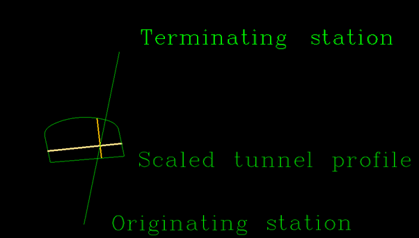
Figure 1: Tunnel cross-section calculation from the data
There are certain constraints on the profile shape caused by the measured grade line offsets. Based on our assumptions, the grade line offsets are direct measurements taken into account while the design profile is a desired shape that may or may not be achieved. Both horizontal and vertical scales of the profile can be flexible.
Consider a profile with four measured offsets: top, left, bottom, and right. The profile has an inclined bottom line. If the supplied bottom offset is 0, this profile design can't be used because it can't be scaled to satisfy the desired offsets. In fact, when the bottom offset is 0, the measurement should be taken at the lowest corner of the profile and the profile can't be scaled to achieve non-zero left and right offsets.
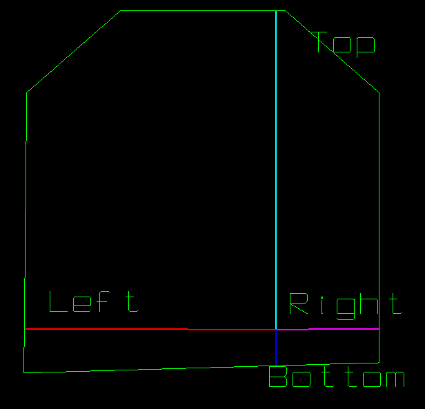
Figure 2: Tunnel profile constraints
Area
This is an optional alphanumeric field for storing the area in which the drive lies (level name for instance).
Book
This is an optional alphanumeric field for storing the drive name or book number.
Date
This is the current date. You can choose to select the format of date according to international, US, or European standards.
Click Apply and Run. The required UG tunnel profile is created.
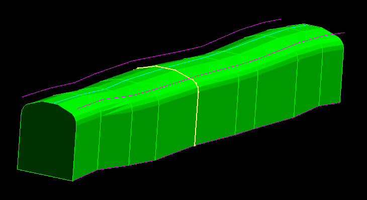
Figure 3: UG drive with tunnel profile
Survey stations
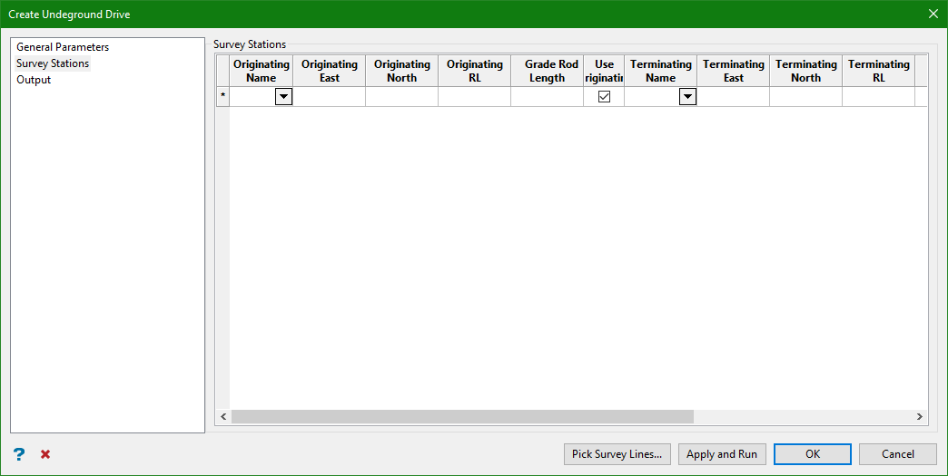
You can manually enter the data for originating and terminating survey stations. Enter the name, easting, northing, RL and Grade Rod Length manually or copy from an excel sheet and paste it on to the grids.
Grade Rod Length
This is the length of the rod hung vertically from the originating and terminating survey stations. The bottom of the road is the originating or terminating point on the grade line and has an elevation of: RL - Grade Rod Length.
Use Orig.
This option specifies the use of originating station as chainage reference.
Use Coords
This option specifies the use of coordinates for terminating station as chainage reference rather than bearing and gradient from the originating station. Selecting this option disables Bearing and Gradient columns.
Note: When this option is checked, the cells shouldn't have empty terminating station name.
Bearing/Gradient
The bearing is a compass bearing and must be entered in the DDD.MMssddd format, for example, 23.45517 is 23 deg 45' 51.7". The gradient may be entered as a decimal degree, a ratio, or a percentage. Note that 45.0, 1:1, and 100% are all specifying the same gradient.
Note: When users choose to use bearing and gradient from the originating station rather than coordinates of the terminating station for the direction of the survey line, the Use Orig. and Term. Name columns are disabled. This is because the direction of the survey line is given as the direction from the originating station.
Grade Line Offsets
Clicking on the grid displays the Grade Line Offsets panel. This panel allows to enter a set of seven values along with the option to pick survey lines. Each set defines a single drive cross-section and consists of a Left, Right, Back, Floor, Chainage, Bearing, and Gradient value.
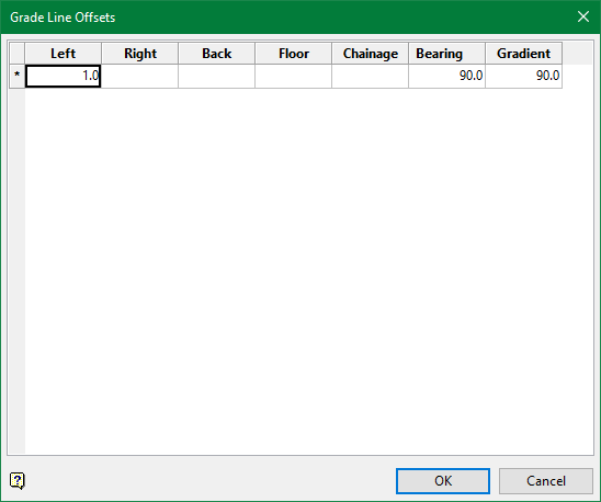
Left
This is the distance from the grade line to the left wall (to the left when looking in the direction of the cross-section).
Right
This is the distance from the grade line to the right wall (to the right when looking in the direction of the cross-section).
Back
This is the distance from the grade line to the back or top wall (upwards when looking in the direction of the cross-section).
Floor
This is the distance from the grade line to the floor or bottom wall (downwards when looking in the direction of the cross-section).
Chainage
This is the distance along the grade line (positive distance in the positive grade line direction) from the specified reference point, that defines the chainage point—the point from which the Left, Right, Back, and Floor offsets are measured.
Bearing
This is the angle (in decimal degrees between 0 and 180) from the positive grade line in axis, measured clockwise to the plane of the drive cross-section.
For example: 90 degree is normal to the grade line, 0 degree has the left and right offsets positioned on the grade line (right ahead of left), and 180 degree has the left and right offsets positioned on the grade line (left ahead of right).
Gradient
This is the angle (in decimal degrees between 0 and 180) from the positive grade line axis, measured downwards to the plane of the drive cross-section.
90 degree is normal to the grade line, 0 degree has the cross-section pointing upwards, and 180 degree has the cross-section pointing downwards.
Output
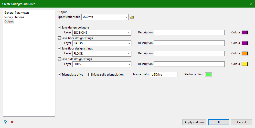
Specifications File
Select this check box to save the drive data to a UG Drive specification file. You can either enter the spec file, or select one from the drop-down list.
There are a number of options to save the strings in different layers. Enter the layer name, add a layer description, and choose a colour to distinguish between each resultant strings.
Save Design Polygons
Select this check box to save the design polygons (that is, the cross-sections) onto the screen.
Save Back Design Strings
Select this check box to save the back (roof) design strings (that is, the lines joining the top corners of the cross-sections).
Save Floor Design Strings
Select this check box to save the floor design strings (that is, the lines joining the bottom corners of the cross-sections).
Save Side Design strings
Select this check box to save the side design strings (that is, the lines parallel to the survey left and right offset values).
Triangulate UG Drive
Select this check box to create an open ended, solid representation of the drive. You can add a name prefix to the resultant triangulation and also specify a colour.
Make solid triangulation
Select this check box to create a close ended, solid triangulation of the drive.
Naming convention of the output triangulation
-
If bearing and gradient is used, the output triangulation name is <prefix><originating station name>_<bearing of terminating station>_<gradient of terminating station>. Eg. UGDrive1ss_110.0_30.0.00t
-
If Use Orig. is checked, the triangulation name is <prefix><originating station name>_<terminating station name>.00t
-
If Use Orig. is unchecked, the triangulation name is <prefix><terminating station name>_<originating station name>.00t
Select Apply and Run.
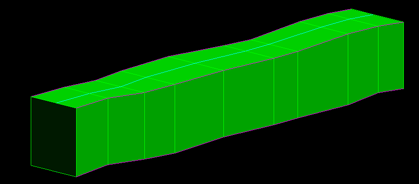
Figure 4: UG Drive without tunnel profile
