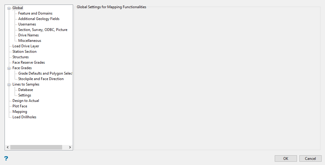
Configuration
Use this option to define adjustable settings for the mapping tools.
Instructions
On the Face Mapper menu, point to Setup, then click Configuration.
Note: You can save your work at any time by clicking the OK button.
Global features that apply to multiple tools.
Features and Domains
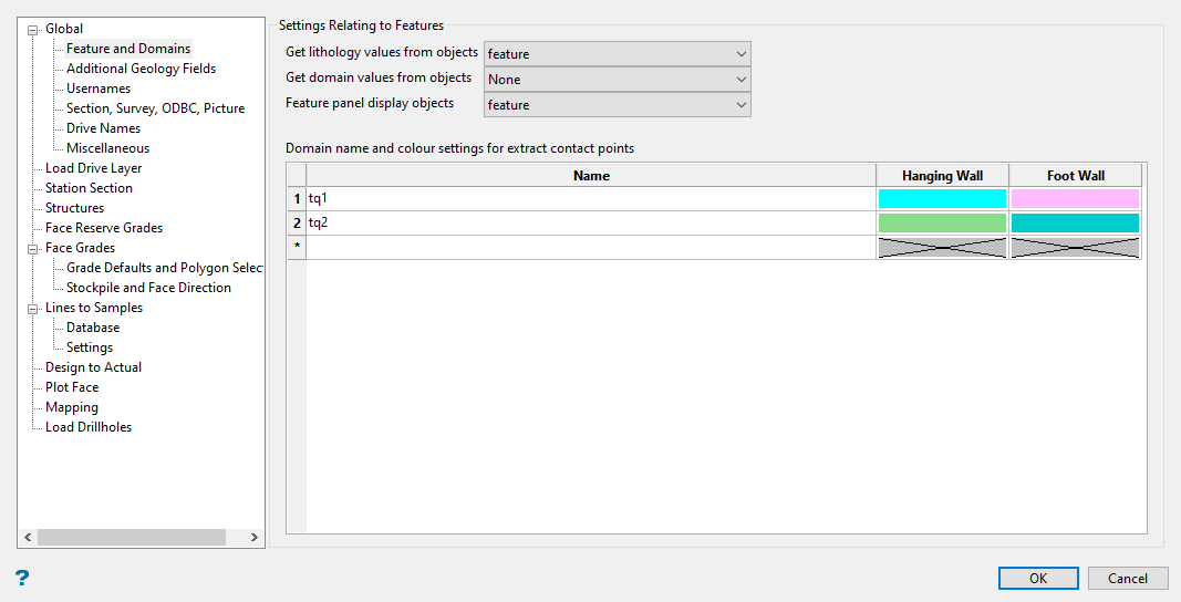
This panel defines settings related to the Feature (.ftd) files created using the Face Mapper > Setup > Create Feature Files tool and allows domain definition.
Follow these steps:
-
Select where to read the lithology value from on each of the face mapping polygons using the Get Lithology values from objects drop-down list. This relates to the values defined in Face Mapper > Setup > Create Feature Files and can be set as:
-
description – this will read the object description as the lithology value.
-
feature – this will read the feature name as the lithology value.
-
group – this will read the group name as the lithology value.
-
-
Select where to read the domain value from on each of the face mapping polygons using the Get Domain values from objects drop-down list. This relates to the values defined in Face Mapper > Setup > Create Feature Files and can be set as:
-
None – this will not read any of the polygon attributes for the domain value.
-
description – this will read the object description as the domain value.
-
group – this will read the group name as the domain value.
-
-
Select where to read the values displayed on the feature selection panel displayed by Face Mapper > Mapping > Feature Lines and Face Mapper > Mapping > Feature Replace using the Feature panel displays objects drop-down list. This relates to the values defined in Face Mapper > Setup > Create Feature Files and can be set as:
-
description – this will display the object description on the feature selection panel.
-
feature – this will display the feature name on the feature selection panel.
-
group – this will display the group name on the feature selection panel.
-
-
Enter the Domain names and colour settings for extract contact points into the table. This allows domain names to be defined for use with the Face Mapper > Mapping > Line To Samples and Face Mapper > Post Processing > Flag Contact Points tools, as well as colours for Hanging Wall and Foot Wall points that can be extracted using the Face Mapper > Post Processing > Extract Contact Points tool.
Table definitions
Name
The desired Domain names.
Hanging Wall
The desired colour for the Hanging Wall points to be created for each Domain.
Foot Wall
The desired colour for the Foot Wall points to be created for each Domain.
Additional Geology Fields
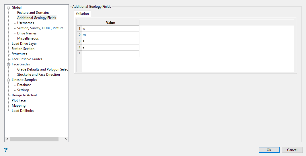
Allows the acceptable values for each additional geology text field defined in Face Mapper > Setup > Create Resources(see Samples database > Additional geology fields ). These fields are selectable when using the Face Mapper > Mapping > Line To Samples.
Follow these steps:
-
Enter a Value for each field.
Example: If an additional geology field called “Foliation” has been defined, acceptable values set in this panel might be “w”, “m”, “s”, “e” to denote the intensity of foliation.
Only additional geology text fields will be visible in this panel because any numeric field values can be entered directly into the Face Mapper > Mapping > Line To Samples panel.
Usernames
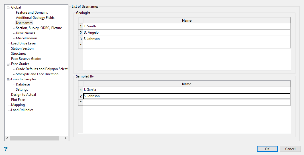
Allows the names of geologists and samplers to be defined.
Follow these steps:
-
Define the list of geologists that will be available in the drop-down lists in the Face Mapper > Mapping > Station Section, Face Mapper > Mapping > Walls Mapping, and Face Mapper > Mapping > BacksMapping panes.
These can be names or initials, to match any existing logging codes.
Note: A maximum of 10 characters can be entered, as this aligns with the drafting sheets utilized in Face Mapper > Post Processing > Plot Face.
-
Define the list of samplers that will be available in the drop-down lists in the Face Mapper > Mapping > Line To Samples pane.
If the Sampled by field is enabled in Face Mapper > Setup > Create Resources(see Samples database > Sampled by), then this option will be available to define the list of geologist or technicians that will perform sampling. These can be names or initials, to match any existing logging codes.
Note: A maximum of 10 characters can be entered, as this aligns with the drafting sheets utilized in Face Mapper > Post Processing > Plot Face.
Section, Survey, ODBC, Picture
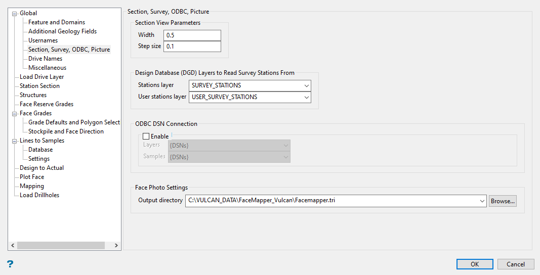
Defines the following:
-
parameters used by any tools that place the screen into section view
-
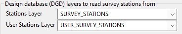
the design database (
.dgd) layers to read survey stations from -
the ODBC database connections
-
settings related to face photos
Follow these steps:
-
Enter the Width and the Step size of the section view in the space provided.
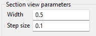
Width - The section width in section view will be the viewable portion of the section in both the forward and backward directions.
Step size - The step size in when in section view. e.g.
Example: If set to “0.1”, then pressing the Page Up or Page Down keys on your keyboard will move the current slicing plane 0.1m forward or backwards, respectively.
-
Select the survey Station Layers in which survey stations will be read from.
-
Select the User Stations Layer in which user defined reference points will be read from.
-
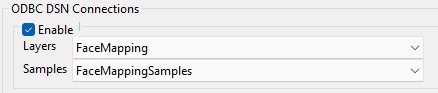
Click Enable to define any ODBC Database Connections.
This defines the ODBC database connections (see ODBC Data Source Administrator).
-
Select the Layers to save the mapping polygons into when the ODBC DSN connection for the SQL database is enabled.
-
Select the ODBC DSN connection for the SQL database to save the mapping Samples into.
-
Select the Output directory for your pictures. This defines the folder that face photos registered using the Face Mapper > Pictures > Picture Display tool will be saved to. This folder will contain a .jpg, .ireg, and .00t file for each face photo registered.

Note: The folder must have a “.tri” suffix, to denote a triangulation subdirectory folder within the Vulcan project directory.
Drive Names
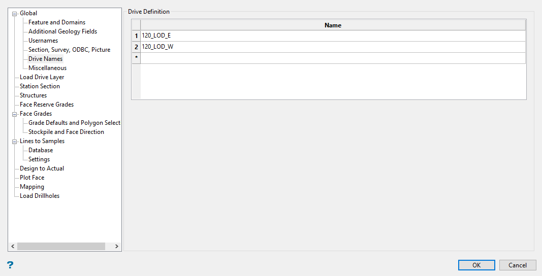
Defines the currently active underground drive headings. These will be available from the Drive drop-down menu in the Face Mapper > Mapping > Station Section, Face Mapper > Mapping > Walls Mapping, and Face Mapper > Mapping > BacksMapping panes.
Follow these steps:
-
Enter the drive names in the space provided.
Note: The drive names are limited to 40 characters each.
Note: Once a drive no longer having any mapping needed, it can be removed from this list. Only the currently active headings need to be in here.
Miscellaneous
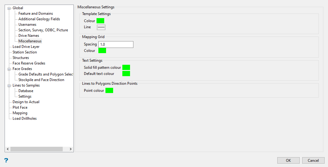
Defines other miscellaneous global settings.
Template settings - Defines the settings for the mapping templates created by the Face Mapper > Mapping > Station Section, Face Mapper > Mapping > Walls Mapping, and Face Mapper > Mapping > BacksMapping tools.
|
Colour |
The colour that will be applied to the mapping template polygon that is created. |
| Line | The line style that will be applied to the mapping template polygon that is created. |
Mapping Grid - Defines the settings for the reference grid lines created by the Face Mapper > Mapping > Station Section and Face Mapper > Mapping > Walls Mapping tools.
|
Spacing |
The spacing at which the reference grid lines will be created. |
|
Colour |
The colour that will be applied to the reference grid lines created. |
Text settings - Defines the settings for text objects created by various tools.
|
Solid fill pattern colour |
The colour that will be applied to mapping polygon labels when the polygons have a solid fill pattern applied. |
|
Default text colour |
The default colour applied to other text labels created by various tools. |
Lines To Polygons direction points - Defines the settings for the Face Mapper > Mapping > Lines To Polygons direction selection points.
|
Point colour |
The colour that will be applied to the direction selection points. |
Load Drive Layer
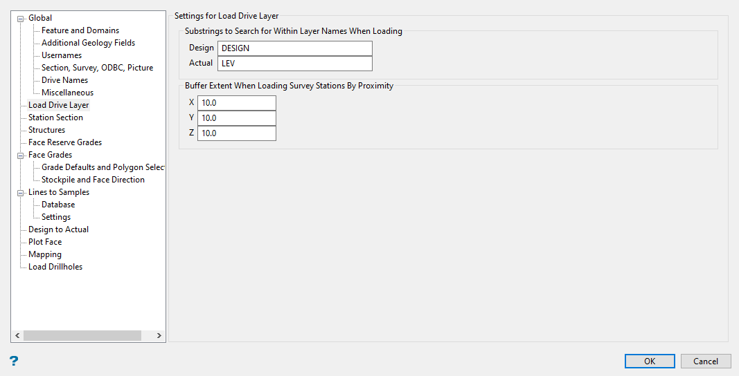
Defines settings specifically related to the Face Mapper > Mapping > Load Drive Layer tool.
Follow these steps:
-
Enter the naming convention substring for the design file layers into the space labelled Design. You must have this within the layer name to distinguish it as a design file. It can be things such as “DESIGN”, “MPA”, “LDP” etc.
Note: When loading layers, the Face Mapper > Mapping > Load Drive Layer tool will search for the defined substring within the layer names in the design database for the option selected.
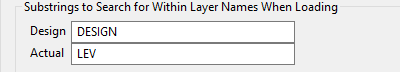
-
Enter the naming convention substring for the actual/survey pickup file layers into the space labelled Actual. You must have this within the layer name to distinguish it as a design file. It an be things such as “LEV”, “ASBUILT”, “PICKUP” etc.
-
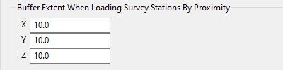
Enter the XYZ extents (in DG1 units) to build a buffer around the loaded level layer.
Station Section
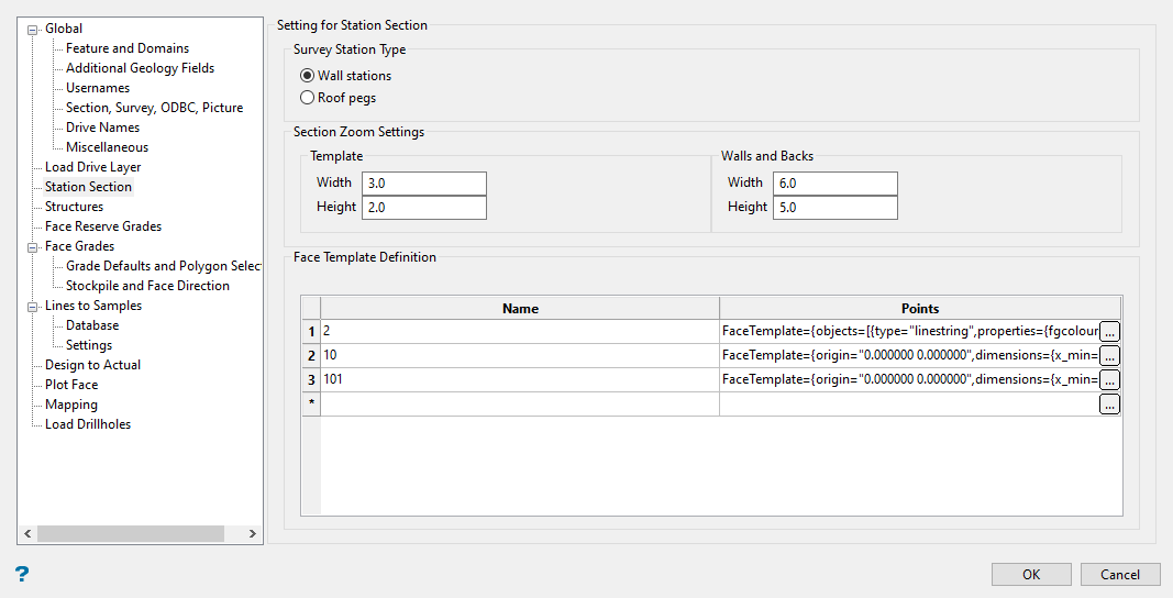
Defines settings specifically related to the Face Mapper > Mapping > Station Section tool.
Follow these steps:
-
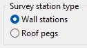
Select if the mine uses survey stations in the walls or survey pegs (survey stations) on the roof instead.
-
Define the level of zoom when creating the section view. These can be edited if required to ensure zoom settings are best suited for the device being used for mapping.
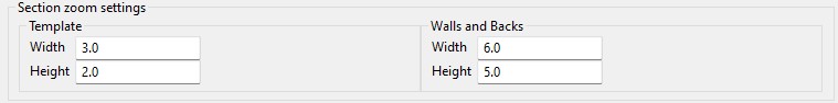
Section zoom settings
Template
The zoom settings that will be used when the Walls and backs option is checked off in the Station Section panel.
Walls and Backs
The zoom settings that will be used when the Walls and backs option is checked on in the Station Section panel.
-
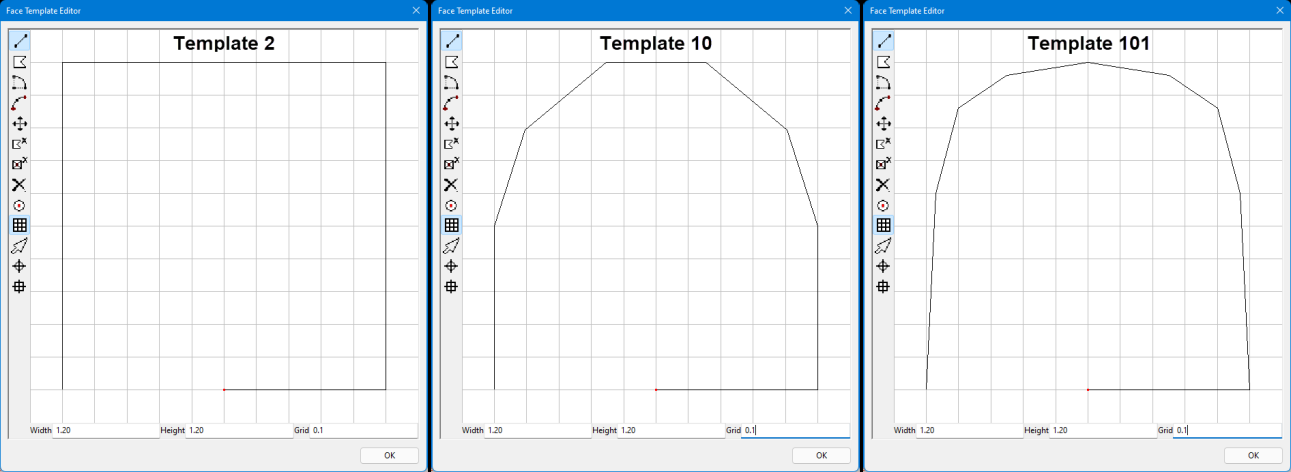
Enter a Name that will store the point coordinates for the face templates used to build the drive profile by Station Section. These are based on primitives and are numbered accordingly. These names can be renamed if desired.
Note: The start point is the origin [0,0] which is the mid point of the bottom which gets placed on the centreline of the drive, the 2nd point is the bottom most right, and the last point is the bottom most left. Users can define their own templates in here, but the height and width ranges must be between 0-1.
-
Enter the point coordinates by double-clicking on the cell labelled Points, or by clicking the
 icon. A template diagram will be displayed, allowing you to design the drive profile. When you have completed the profile, click OK to close the template diagram. The information will be entered into the cell automatically. (For information about creating and editing drive profiles, see Model > Primitives > Create/Edit Primitives.)
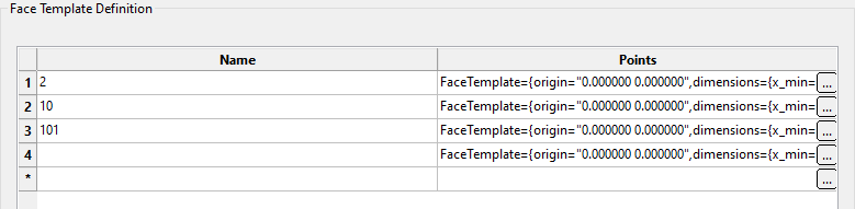
Structures
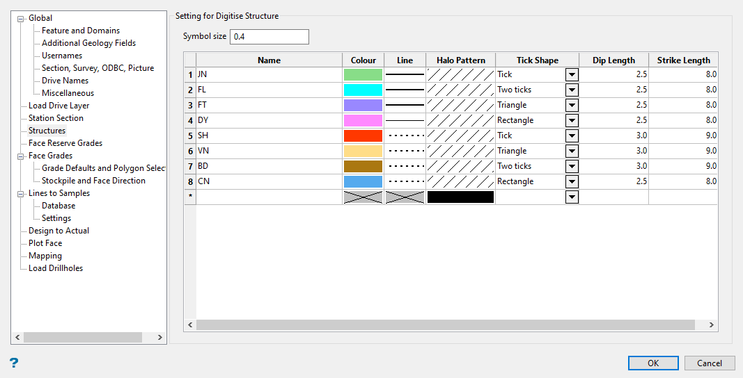
Defines the desired settings for geological structures that can be captured using the Face Mapper > Mapping > Digitise Grades tool and viewed as structural symbols and/or oriented halos using the Face Mapper > Tools > Display Structures tool.
Follow these steps:
-
Enter the Symbol size. This is the size at which the symbol will be created by Face Mapper > Mapping > Digitise Grades.
-
Complete the table defining the shape and look of the symbols.
Name
The code for the structure. There is a 2 character limit for these codes.
Colour
The colour for structural symbol.
Line
The line style for the structural symbol.
Halo pattern
The pattern applied to the oriented ellipse polygons displayed using Face Mapper > Tools > Display Structures.
Tick shape
The shape of the line segment (tick mark) created on the dip axis of the structural symbol displayed using Face Mapper > Tools > Display Structures.
Dip length
The length of the line segment (tick mark) created along the dip axis of the structural symbol displayed using Face Mapper > Tools > Display Structures.
Strike length
The length of the line segment created along the strike axis of the structural symbol displayed using Face Mapper > Tools > Display Structures.
Face Reserve Grades
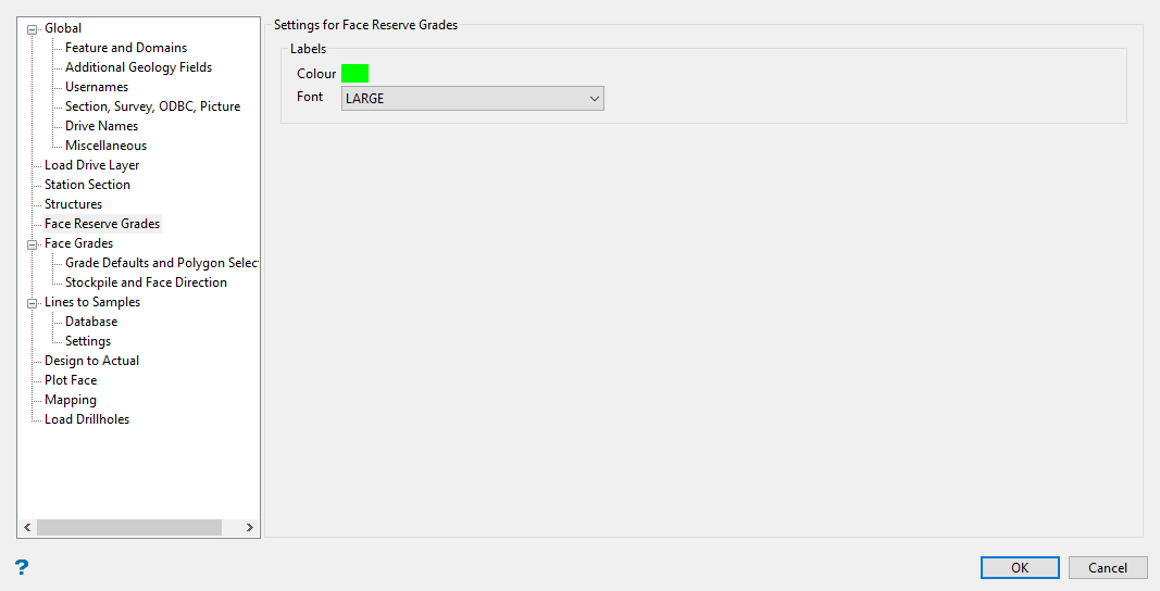
Settings that relate specifically to the Face Mapper > Mapping > Face Reserve Grades tool.
Follow these steps:
-
Select the colour index in the colour palette for the labels.
-
Select the font style that will be used for the labels.
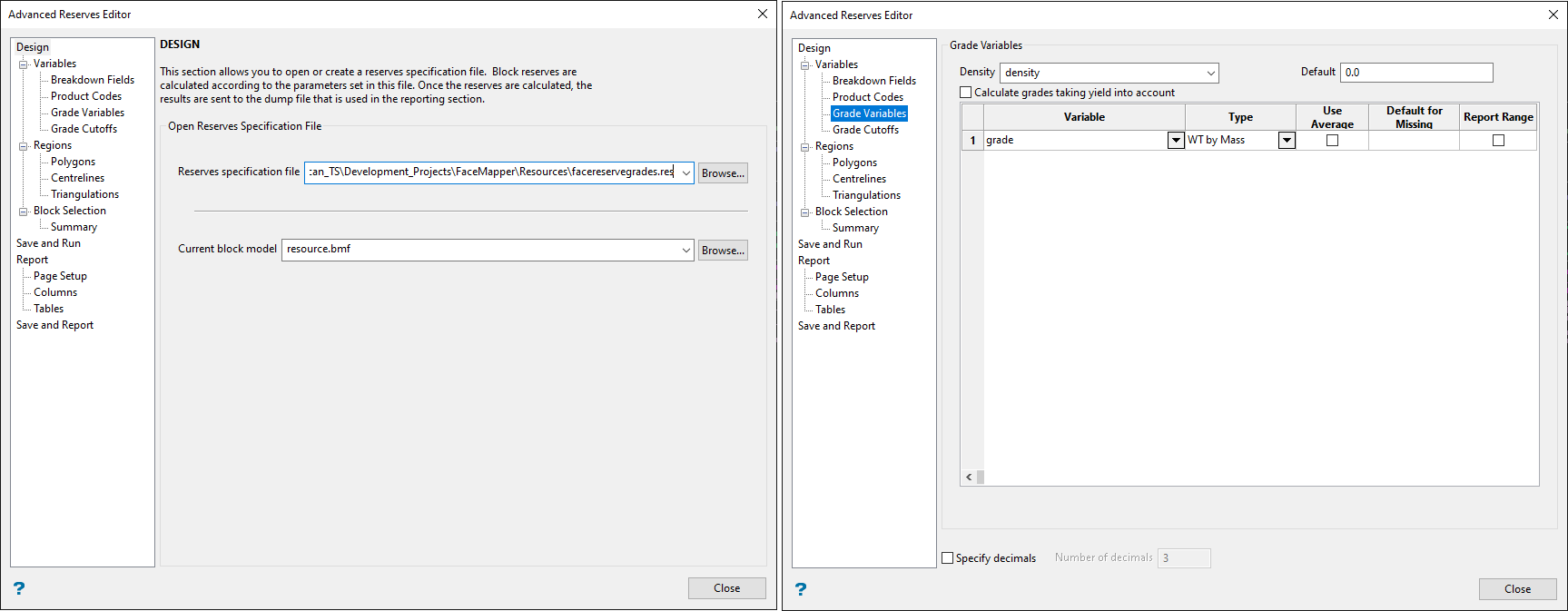
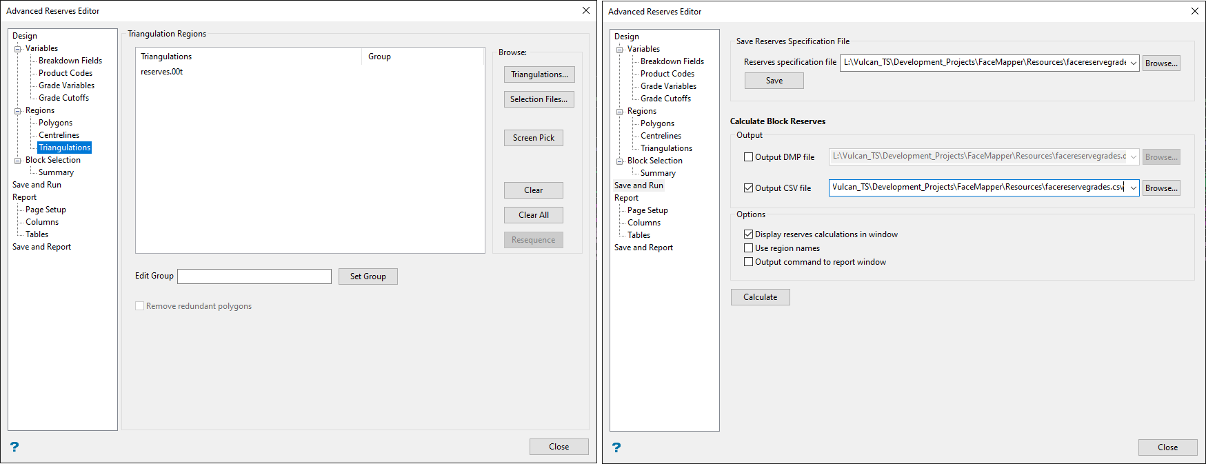
The following settings are how the .res file should be configured in order to run the Face Mapper > Mapping > Face Reserve Grades tool correctly. A facereseregrades.res file gets created automatically by the Create Customisation File. The grade and density variables in this file need to be checked to ensure they match the block model(s) being used. These block model variable names need to match the Element names defined in the Face Mapper > Setup > Create Resources panel in order to correlate correctly.
Estimated grade defaults
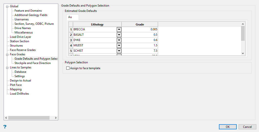
Settings that relate specifically to the Face Mapper > Mapping > Face Grades tool.
Follow these steps:
-
Define the Lithology and Grade by entering your data into the table. These store the estimated grade values to be used by the Face Mapper > Mapping > Face Grades tool for each feature.
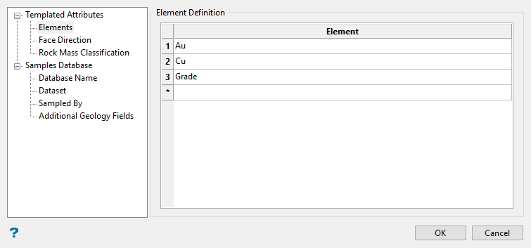
NoteThe table headings are defined in the Templated Attributes > Elements section of the Face Mapper > Setup > Create Resources tool.
-
Enable Assign to face template if you want to assign the grades to the face template instead of the lithology polygons.
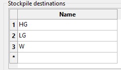
Stockpile destinations
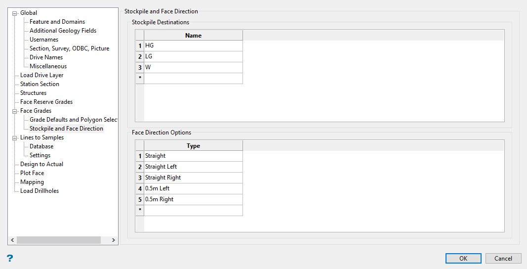
Stores the stockpile values that will appear in the stockpile drop-down list in the Face Mapper > Mapping > FaceGrades panel.
Follow these steps:
-
Enter the names of the stockpile destinations into the table.
-
Enter the face direction settings for defining geology control changes of direction.
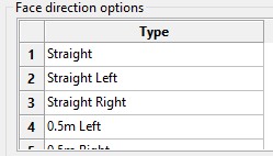 Note
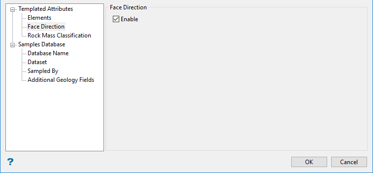
NoteThis is available when the Face Direction option is enabled in the Face Mapper > Setup > Create Resources tool. If that option is not enabled, the table will be displayed but cannot be edited.
Database
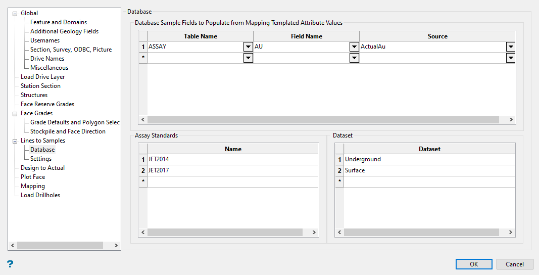
Settings that relate specifically to the Face Mapper > Mapping > LineToSamples tool.
Follow these steps:
-
Select the Table Name from the drop-down list. This defines which table to write into in the Isis database.
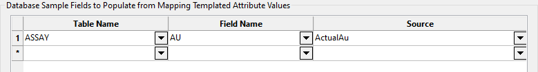
This allows the definition of which templated attribute(s) can be read from the Face Mapping Polygons and written to the equivalent face sample line interval in the isis database.
-
Select the Field Name from the drop-down list. This defines which field in the isis database to write the values into.
-
Select the Source from the drop-down list. This defines which templated attribute will be written to the isis database.
-
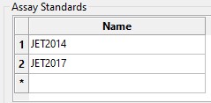
Enter the Assay Standards used under the Name column. These store the name values that can be selected for the Standard cells in the Face Mapper > Mapper > Line To Samples panel.
-
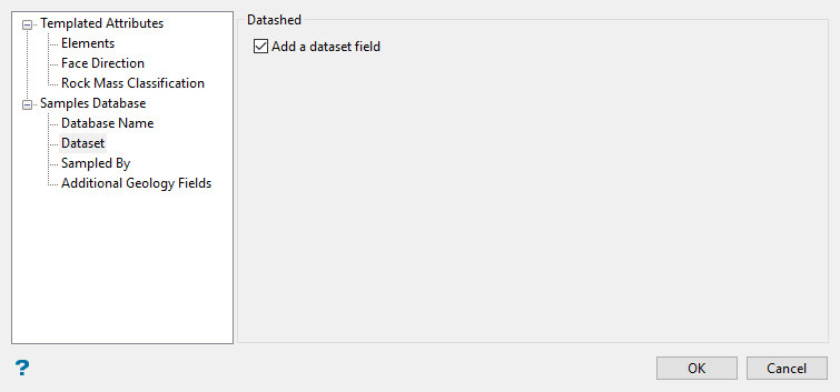
Enter the Datasets used to hold your assay values. This defines the dataset field values that will be available for selection in the Face Mapper > Mapping > Lines To Samples panel.
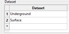 Note
NoteThis is available when the Add a dataset field option is enabled in the Face Mapper > Setup > Create Resources tool.
Settings
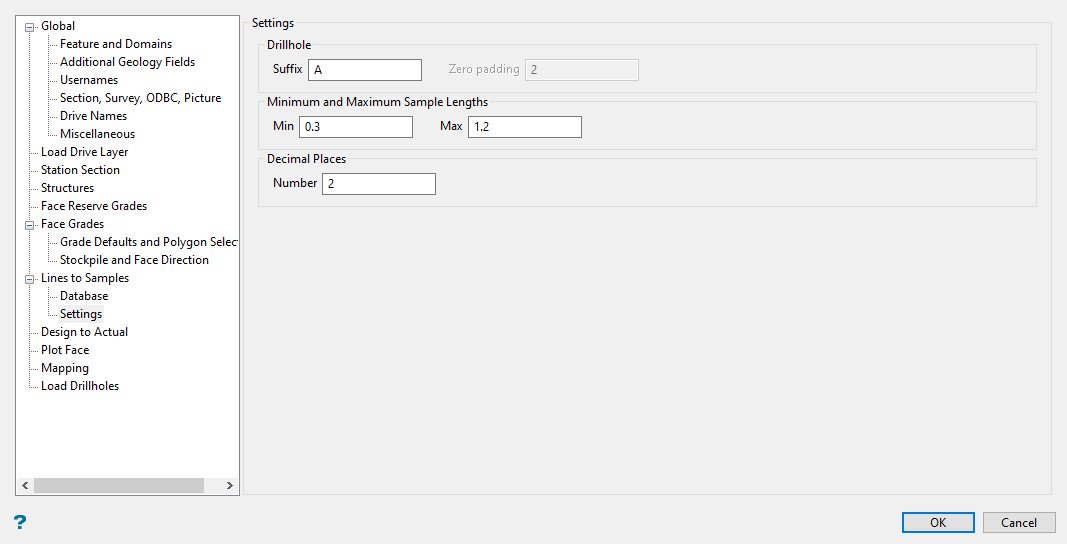
Drillhole settings that relate specifically to the Face Mapper > Mapping > LineToSamples tool.
Follow these steps:
-
Enter a Suffix. This can either be a text suffix ( for example, “A” or “G”) or numeric (“1”). This suffix will be used first and iterated for each subsequent extra sample line created, and defines the suffix that will be applied to the drillhole name when creating multiple sample lines on a face.
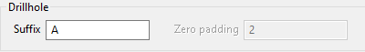
-
Enter the Zero padding to use if the suffix is numeric. This defines how many zeros will be appended to the suffix.
Example: With a zero pad of
2and a suffix of1the suffix that gets appended would be001,002, etc. -
Enter the Minimum sample length allowed. This defines the minimum sample length allowable when using the Enforce min/max option in the Face Mapper > Mapping > LinesToSamples tool.
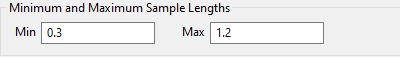
-
Enter the Maximum sample length allowed. This defines the maximum sample length allowable when using the Enforce min/max option in Face Mapper > Mapping > LinesToSamples tool.
-
Enter the Number of decimal places. This defines the number of decimal places shown in the From and To columns in the Face Mapper > Mapping > LinesToSamples tool.
Design To Actual
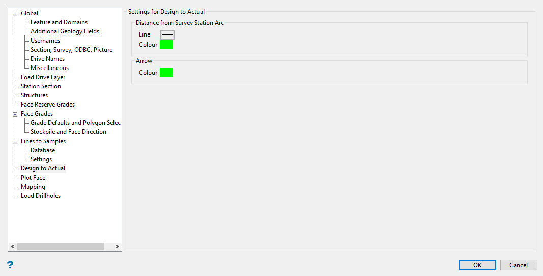
Settings related specifically to the Face Mapper > Post Processing > Design To Actual tool.
Follow these steps:
-
Select the Line style for the arc created that represents the distance from the survey station to the face.
-
Select the Colour applied to the arc.
-
Select the Colour for the arrow denoting the distance.
Plot Face
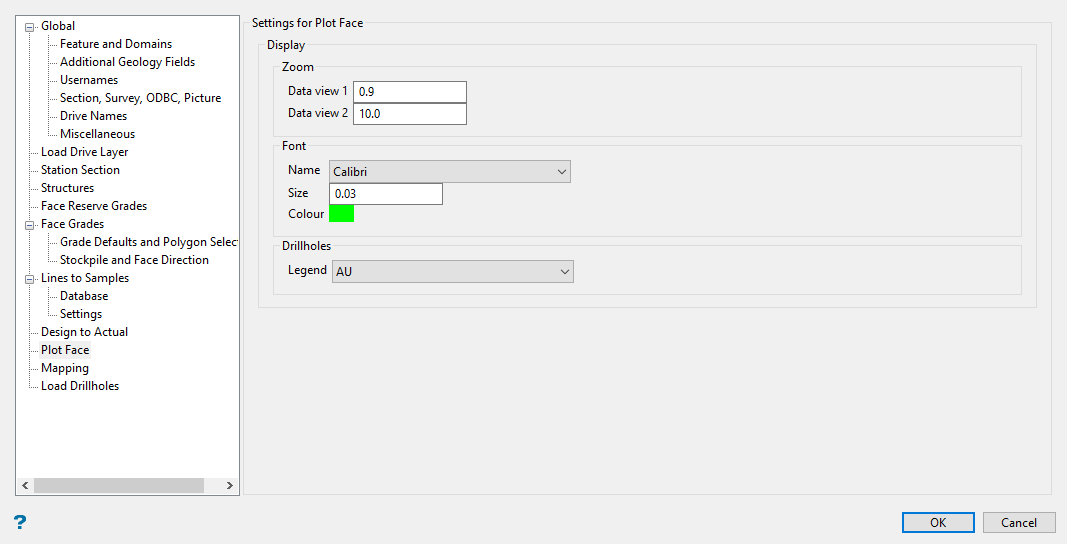
Settings that relate specifically to the Face Mapper > Post Processing > Plot Face tool.
Follow these steps:
-
Enter the Zoom factor to use on the face sketch into the space labelled Data view 1.
-
Enter the Zoom factor to use on the location sketch into the space labelled Data view 2.
-
Select the font style Name applied to the labels used in the Location Sketch, along with the Size and Colour.
-
Select the Legend used to display the drillholes.
Mapping
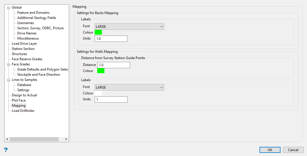
Settings that relate specifically to the Face Mapper > Mapping > Backs Mapping and the Face Mapper > Mapping > Walls Mapping tools.
Follow these steps:
-
Set the Font, Colour, and Units (frequency of the tick marks in DG1 units) for the labels. These store the settings for the text and tick marks for both the major and minor labels that get created along the mapping template.
-
Enter the Distance from survey station guide points. This is the distance interval at which the guide points will be created.
Note: The Distance from Survey Station Guide Point settings relate to the guide points drawn to help select forward and back boundary points.
-
Select a Colour for the guide points and guide point distance labels.
Load Drillholes
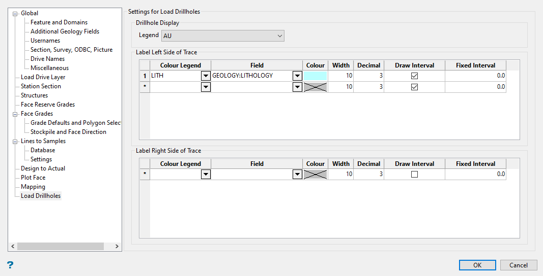
Settings that relate specifically to the Face Mapper > Tools > Load Drillholes tool. These settings mimic that of a multi-label spec file (.mls).
Follow these steps:
-
Select the Drillhole Legend. The drillhole legend is used to display the drillhole.
ImportantA legend must exist in the current schema file (.scd) with appropriate values to suit the lithologies defined in the Face Mapper > Setup > Create Feature Files tool. -
Set the display parameters to Label left side of trace.
Note: The Configuration panel can be closed and progress will be saved but it will not count as complete without defining the labels on the left side. Any option that requires the configuration to be complete will be blocked.
Colour Legend
The desired colour legend to apply to the text labels. A legend must exist in the current schema file (
.scd) with appropriate values to suit the lithologies defined in the Face Mapper > Setup > Create Feature Files tool.Field
The field to display values for from the samples drillhole database.
Colour
If desired, a single colour can be defined to colour all text labels the same colour.
Width
The width/spacing of the label column.
Decimal
The number of decimal places to display for numeric fields.
Draw Interval
Select this box if you want to display interval markers along the drillhole trace.
Fixed Interval
This field allows a fixed depth labelling interval to be specified. If a depth is specified, then the drillhole labels will be produced only in increments of this depth.
-
If desired, define the parameters to label the right side of the trace.
-
Click OK to save the changes to the specification file and close the Configuration panel.
