Mining Blocks Generation Setup
The functionality is separated in two phases – setup and block creation.
At the setup phase the user creates a specification, which describes the input data – triangulations and polygons, as well as the configuration and location of boundaries and benches, and the location and hierarchy of the output triangulation files and design layers.
Workflow
The Mining Blocks Generation is organised in two phases – Setup and Block Creation.
Setup
The setup stage produces the mining stage and benches triangulations, all trim, ramp and production zone polygons, and other design objects and triangulations instrumenting the process.
Create stage solids
To create mining stage triangulations, open the Setup panel and navigate to the Pit Design tab. On the Open Pit menu, point to Mining Blocks Generation, then click Setup to display the following panel.
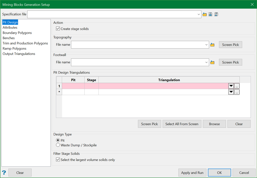
Pit Design
Select the Create stage solids checkbox.
This will enable the rest of the options on the tab and ensure that stage triangulation solids are created at the end of the setup on Apply and Run.
Select topography triangulation from the drop-down list, browse to file location, or pick from the screen.
Select a footwall surface from the drop-down list, browse to file location, or pick up from the screen. This is similar to the topography except that the blocks are limited at the bottom of the pit.
Select pit/dump design surfaces or solids to fill in the Pit Design Triangulations table and enter the preferred names for the pit and mining stages in the same table.
Select the mine Design Type – pit or waste dump/stockpile.
If selected Select the largest volume solids only option will filter out disconnected shells if any, and save only the one with the largest volume as a stage solid triangulation.
All disconnected shells are saved in the project hierarchy for user reference.
The resulting stage triangulations are saved in the Stage Triangulations folder, specified at the Output Triangulations tab.
Attributes
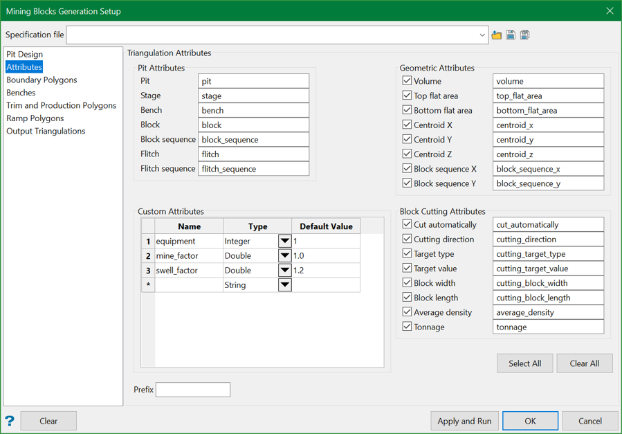
The triangulation attributes on the Attributes tab are offered in three groups.
Pit Attributes
The attributes in this group are automatically added to triangulations created during the mining block generation, such as stage, bench, block solids, where applicable. For example, the pit and stage attributes are added to all triangulations; the bench attribute is added to bench and block triangulations; the block identifier, and block sequence attributes are added to the final mining block solids.
Geometric Attributes
The geometric attributes are calculated and added automatically to most of the triangulations created during the process, and always to the final block solids.
The attributes are optional and each can be selected to use or not, by the checkbox in front of the attribute name.
Custom Attributes
The user defines the attributes in this group. The attribute name, type and default value need to be specified in the Custom Attributes table.
The custom attributes will be assigned automatically to the block solids with their default values.
The equipment, mine factor, and swell factor attributes are added by default. The attributes and their default values will be assigned to the final mining block solids. These attributes are intended for the Evolution scheduling software. Users may delete or modify the custom attributes default names, types and values.
It is advised to set the equipment attribute type to Integer.
Boundary Polygons
The boundary, or crest polygons, are created and used to create bench solids, and define production, trim and ramp zones.
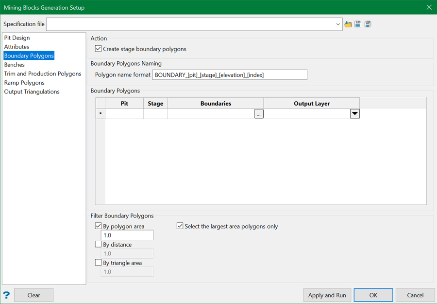
Select the Create stage boundary polygons checkbox at the Boundary Polygons tab to enable the rest of the page and request that the boundary polygons are created on clicking the Apply and Run button.
The polygons will be created, named and saved in design layers as specified on this tab.
The polygon name format may include a prefix to describe the polygon type as stage boundary, and also the name of the pit, stage and elevation to identify the polygon design object. Other attributes such as the polygon position in relation to the bench, like crest, mid-bench or toe, the polygon area, will be added to the boundary polygon design object as part of the Boundary Polygon Template attributes.
The required boundary polygons are specified by the user in the Boundary Polygons table. Each row represents a mining stage for the particular pit. The pair of pit and stage name should be able to uniquely identify the boundary polygons in the table row. The user needs to provide an Output Layer name in the last column by selecting from the available design database layers, or entering a name of a new layer. If an existing layer is selected, it will be overwritten during the boundary polygons creation.
To distinguish from other design layers, when starting a new specification, the Mining Blocks Setup prefills the table with default layers names, including a prefix MBG_ . The user may customise the layer names to their project needs.
The ( …) panel button at the Boundaries column opens a subpanel, where the polygons are specified in more detail.
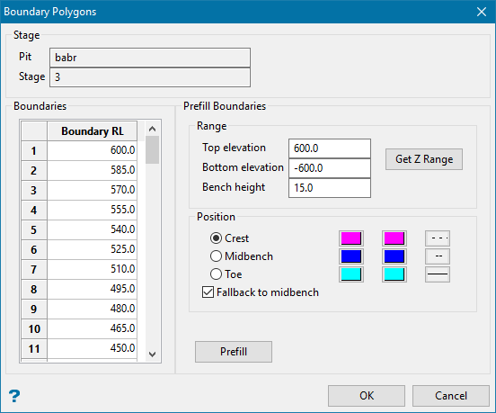
At the top section, the pit and stage names are displayed for information.
The Boundaries table contains the elevations where the user requires polygons to be created. The table provides for both automatic prefill or manual entry.
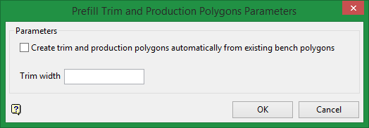
In most cases the Prefill Boundaries section is sufficient to create the entries in the Boundaries table. First, use the Get Z Range button to discover the pit stage top and bottom elevations, or enter the values manually. Enter the Bench height value. Then select the Position of the polygons – at bench crest, midbench, or toe and the preferred line colour or range of colours and style. Click the Prefill button, and the Boundaries table will be populated with equally spaced, by bench height, elevations. Click OK to close the subpanel.
Back at the Boundary Polygons tab, there is also a group of Filter Boundary Polygons options. Each can be used by selecting the checkbox in front of the name and entering a numeric parameter for the filter.
Polygons can be filtered by area. Only polygons with area larger than the minimum area value will be included in the boundary polygons collection.
Polygons can also by filtered by point distance. Polygon points located closer than the distance value to their neighbours will be removed.
Polygons can also be simplified by triangle area. The area of triangles from triplets of consecutive polygon points is calculated and a point is removed if the area is less than the required minimum.
Depending on the pit design shape and topography, there may be more than one polygon produced at the specified elevation. The Select only the largest area polygons only discards polygons with smaller areas, resulting in a single boundary polygon created for each elevation.
Fallback to midbench
Whenever an attempt to generate a boundary polygon at the toe or crest should fail, this allows MBG to fallback to a midbench and try again (in most cases obtaining a valid result). If it can't produce results at midbench, it will continue to the default behaviour and generate an outline of the stage solid as boundary polygon.
This feature is enabled by default and will affect the specified pit and stage boundary.
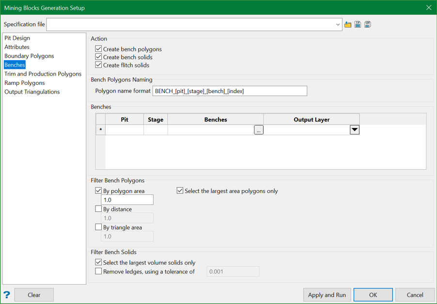
Benches
The Benches tab provides the settings for both bench polygons and the benches.
A bench polygon defines the outline of a bench at particular elevation, usually at the bench toe. The bench polygons are created and used to create bench solids, and define production, trim and ramp zones.
Polygons for all benches in a mining stage are saved in one layer. The user needs to enter a layer name in the Output Layer column by selecting from existing design layers or enter a new layer name. The design layer will be overwritten or created if new.
The Filter Bench Polygons section of the panel tab provides the same types of polygon filter as described in the Boundary Polygons tab.
The Filter Bench Solids option, similar to the Filter Stage Solids option on the Pit Design tab, can calculate volumes of discrete shells, if any, and retain only the one with the largest volume as bench solid.
The Remove ledges option can be used to remove very thin flat areas of the bench, usually a result of small differences between the bench elevation specification and the pit design.
The most important part of the setup is the benches specification. For each mining stage a collection of benches is specified.
The (... ) panel button on each row opens a subpanel to describe the benches in detail.
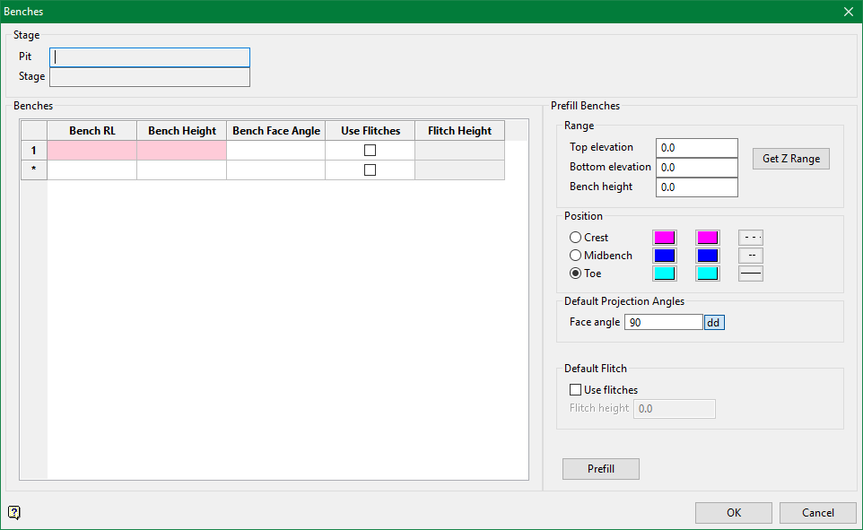
Benches are defined at multiple elevations spanning the entire extent of the stage solid or parts of it.
Similar to the boundary polygons, equally spaced benches can be created quickly using the Prefill Benches section. The bench position defines a reference and the location of the bench polygon and is usually defined at the bench toe.
The Mining Blocks Generation supports benches with different height. The height of a bench at particular elevation can be adjusted entering the values at the Bench RL and Bench Height columns.
The bench face angles can be modified for each bench elevation.
The bench polygons and the bench solids can be created as many times as needed using different parameters.
The created bench solids will be saved in the triangulation files hierarchy specified in the Output Triangulations tab.
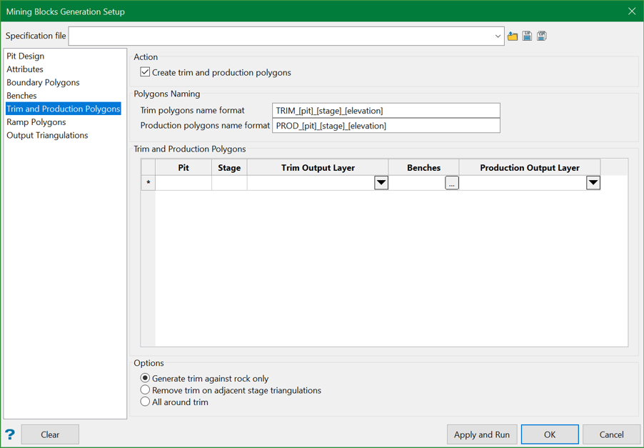
Trim and Production Polygons
One of the objectives of the mining blocks generation setup is to create trim and production zones polygons. The trim zone polygons are optional. They are saved in the design layer specified in the Trim Output Layer column. The production zone polygons are mandatory. They are stored in the design layer specified in the Production Output Layer column.
The Trim and Production Polygons table should always be filled in with the pit, stage, and bench specifications. To automatically fill in the table with the pit, stage, and bench elevations settings, clear the table, switch to the Benches panel tab, and then switch back to the Trim and Production Polygons panel tab.
Three types of trim zone polygons can be created.
The option Generate trim against rock only will remove parts of a full trim trim zone polygon, which are on or above topography, preserving the trim on the outside walls and below topography. A topography surface is required for this option. The sequence of the pit stages in the specification is important as the evaluation begins from the first stage triangulation in the specification.
The option Remove trim on adjacent stage triangulations will remove parts of the trim where the pit stage triangulations is touching another stage triangulation.
The option All around trim will create full trim zone polygons.
The (... ) panel button in the Benches column opens a subpanel where a detail description of the polygon creation parameters is provided. Set the trim width (Offset from Pit Walls) to zero for each bench where trim polygons are not required.
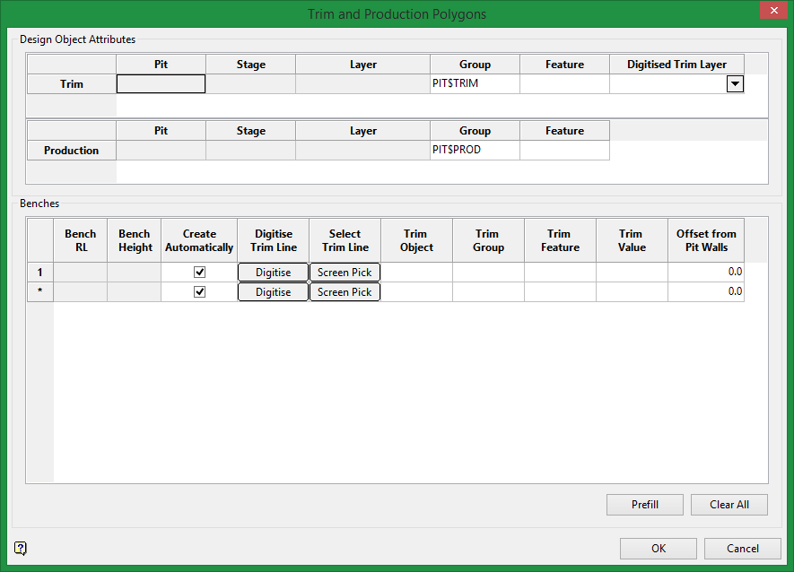
The Benches table is automatically populated with all bench definitions, as specified at the Benches tab. All bench elevations and bench heights are displayed in the first two columns for reference. Rows can be deleted if not needed.
If required, the trim zone can be defined using the different tools on the panel:
The trim zone can be automatically created at a distance from the bench boundary if the Create Automatically checkbox is selected and a positive value entered in the Offset from Pit Walls column.
The trim zone can be digitised using the Digitise button in the Digitise Trim Line column.
If there is an existing trim zone polygon loaded on the screen, it can be selected using the Screen Pick button in the Select Trim Line column. The Create Automatically checkbox should be cleared.
Any selected or digitised design objects are copied and assigned attributes describing the pit, stage and bench they will be used for.
A trim zone polygon will not be created if the trim width is set to zero.
The Prefill button provides a simple interface to prefill the whole Benches table setting the automatic trim creation and the trim width parameters.
The production zone polygons are always recreated by excluding the trim and ramp zone polygons from the bench boundary.
All zones polygons are named and assigned templated design attributes to identify the location they represent.
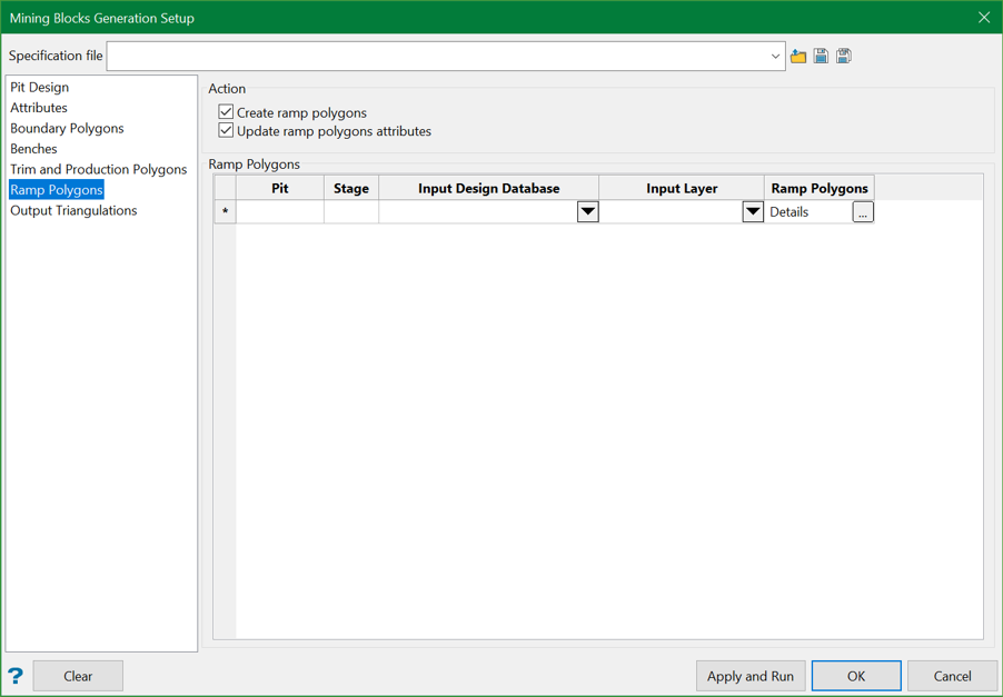
Ramp Polygons
The ramp polygons are selected from existing design polygons for each mining stage.
The selected existing polygons are copied and assigned attributes.
To associate a ramp polygon with a bench, the ramp polygon should be created at the bench crest elevation or the polygon Z coordinates should intersect the span of the bench height.
When you hit Apply and Run, it automatically discovers the ramp to bench polygons association.
The resulting ramp polygon attributes for pit, stage, and bench will be updated. You can uncheck the Update ramp polygons attribute option if the initial ramp polygons already contain the correct attributes.
Multiple ramps per bench are supported, and the ramp polygons for all benches of a mining stage are saved in a single design layer. Ramp polygons can be selected from different design databases and layers. The ramp polygons design objects must have unique names.
The (... ) panel button in the Ramp Polygons column opens a subpanel, where polygons can be selected from the screen.
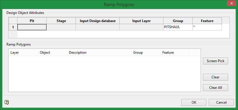
The Ramp Polygons list displays more details about the selected design objects. Individual rows can be removed or the whole list can be cleared using the Clear and Clear All buttons.
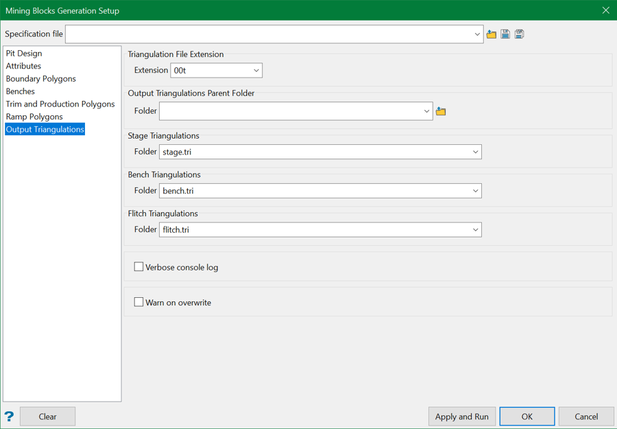
Output Triangulations
The Mining Blocks Generation creates a number of triangulation files which can be classified as stage, bench, flitch, and blocks.
A parent root folder can be defined, under which the hierarchy of triangulation folders will be created.
If the parent folder is not specified, then the hierarchy is created in the current project folder.
You can also choose to display detailed console report to review intermediate steps, parameters, and processing results.
An option to display a warning message on file and folder overwrite is also provided.
At the setup phase the user needs to specify the stage, and bench folder names.
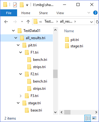
Figure 1: Triangulation folders hierarchy under a parent folder.
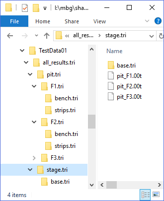
Figure 2: Stage triangulations.
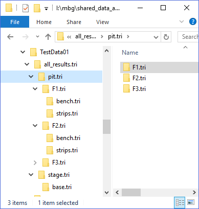
Figure 3: Pit and stages hierarchy.
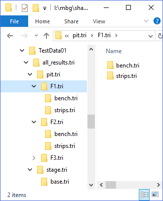
Figure 4: Benches folder in the pit and stage hierarchy.
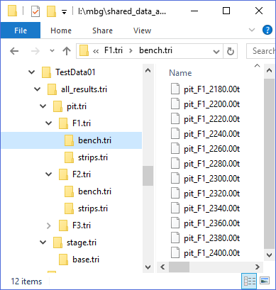
Figure 5: Bench triangulations.
Once all the settings have been configured, click Apply and Run button to run the Mining Block Generation. You can empty all the fields by clicking the Clear button at the bottom-left. This gives two options.
![]()
You can either clear all the fields in this panel or in the Create Blocks panel or both.
