Register
Register a String onto a Triangulated or Gridded Surface
Use the Register option to register strings onto a triangulated or gridded surface. Only those points that fall in the limits of the surface are affected.
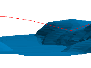
Figure 1: Before Registering
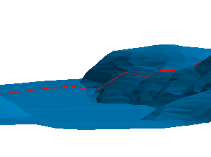
Figure 2: After Registering 2D with Interpolation and Closest Facet
The surface and strings must already be loaded onto the screen. Patterns are not retained by this option. Use the Design > Object Edit > Register option to retain patterns.
Instructions
On the Model menu, point to Triangle Utility, and then click Register.
Select the surface. If there is only one surface model loaded onscreen, then it will be automatically selected.
The String Registration panel is then displayed.
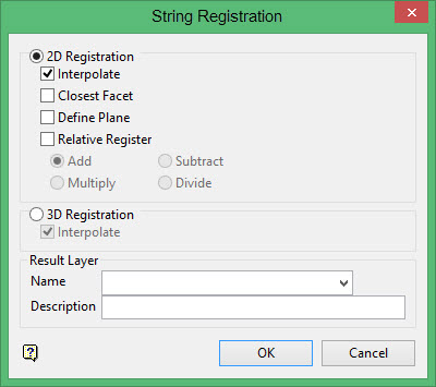
The strings can be registered as either 2D or 3D.
If 3D is selected, then care must be taken as the string to be registered should be close to the triangulation to obtain reasonable results. Digitising the original string by snapping onto the triangulation will give the best results. Care must also be taken near sharp corners in a 3D triangulation. Problems can occur when a corner is greater or equal than 90 degrees. To avoid such problems, the original string should have a point snapped onto the sharp corner, i.e. the string doesn't pass above or through the corner.
In the case of a cube, the string to be registered should have points snapped to the edges of the cube (in the case where the registered string must go from one face to another).
2D Registration
Interpolate
Select this check box to use interpolated X, Y co-ordinates to insert extra points where the registered string crosses a triangle edge or vertex. The W field will be linearly interpolated from the two neighbouring points in the original string. The Name field will always be set to the Name of the preceding original data point.
Closest Facet
Select this check box to register the strings to the closest side of the triangulation. If unticked, then the strings will be registered randomly. This could be one of two sides in the case of a 3D closed triangulation, such as a solid stope.
Selecting this check box does slow down the speed of operation, especially with large strings and triangulations.
Define Plane
Applicable only to 2D registration
Select this option to define a plane for the registering. If this option is not selected, then the XY plane is used. This means that the object's z co-ordinates are altered such that it is draped on top of the model.
You can use this option to define a different plane. An easy way to define the plane is to align the view with the plane that you want to use and then select the Three Point option and use Indicate mode to digitise the three points.
The Register plane panel displays once this panel is completed.
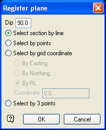
Register plane panel
Dip
The dip is the angle of the section from horizontal. Valid dip angles are between -90° and 90°.
Select section by line
Select this option to define the plane by selecting an existing line and specifying the dip.
Only design strings may be picked and it is not possible to pick a line in an underlay. The direction of the view, and therefore the direction of the stepping, depends on the digitised sequence of the line. The dModel_TriangleUtility_Append_ShadingTabigitised sequence of the line can be reversed using the Design > Object Edit > Reverse option.
Select by points
Select this option to define the plane by digitising two points and specifying the dip.
To locate a point precisely, use the  Snap to Objects or
  Snap to Points modes (on the Digitise toolbar). Points may be snapped onto underlays, such as block model slices or triangulations. If you use
  Indicate mode to select the points, then the points have the current default Z value.
Select by grid coordinate
Select this option to define tModel_TriangleUtility_Append_ShadingTabhe plane by using a specific grid coordinate. The grid co-ordinates can contain up to three decimal places. To achieve the best results for the following three methods, we recommend using the  Zoom Data Extents button (on the Graphics toolbar) in order to view all of the graphics.
- By Easting - Select this option to enter a specific Easting value (X value).
- By Northing - Select this option to enter a specific Northing value (Y value).
- By RL - Select this option to enter a specific RL value (Z value).
Select by 3 points
Select this option to define the plane by digitising 3 points. To locate a point precisely, use the Snap to Objects or Snap to Points modes (on the Digitise toolbar). Points may be snapped onto underlays, such as block model slices or triangulations.
Using this option will allow you to explicitly define the location and orientation of a plane by indicating 3 points. The first two points define the bearing of the plane, and the third point defines the dip of the plane.
Click OK.
Relative Register
Select this check box to change the Z value of the strings that fall in the surface to a valuerelativeto the surface. If unticked, then the Z value of the strings will be set to thesameZ value as the surface.
Points outside the extent of the surface are not affected, i.e. they maintain their original Z value.
The Z level of the strings that fall in the surface can be changed through addition, subtraction, division or multiplication.
Add Z level string = Z level string + Z level surface Subtract Z level string = Z level string - Z level surface Multiply Z level string = Z level string * Z level surface Divide Z level string = Z level string / Z level surface
3D Registration
Interpolate
Select this check box to use interpolated X, Y, Z co-ordinates to insert extra points where the registered string crosses a triangle edge or vertex. The W field will be set to the preceding original data point. The Name field will always be set to the Name of the preceding original data point.
Result Layer
Name
Select the layer that will be used to store the registered strings.
The drop-down list contains the names of all layers in the currently open dgd. If you select an existing loaded layer, then the resulting data will be appended to the nominated layer. If you enter the name of an existing layer that is not currently loaded, then you will need to confirm whether you want to load the layer or replace it.
To create a new layer, enter the layer name. The layer name:
- may contain up to 40 characters.
- must begin with an alphanumeric character [0-9] or [a-z].
- cannot include spaces.
- can include hyphens [ - ], plus signs [ + ], underscores [ _ ], periods/dots [. ].
- can include the special characters of ÁÂÃÀÇÉÊÍÓÔÕÚÜÑ that are used in the Spanish and Portuguese languages.
Description
Enter a description to further describe the contents of this layer. The description can be up to 80 alphanumeric characters and may include spaces. If a description is not entered, then a default description will be used instead. If the chosen layer already has an assigned description, the description displays when the layer is selected. Existing layer descriptions can be overwritten.
Click OK.
The Multiple Selection box is then displayed. From this box, choose your method of selecting strings and select the strings. The strings are then registered onto the surface and assigned to the nominated layer.
