Merge Surface Models
This option allows users to vary the resolution of surface models (grids or triangulations) to reflect the input data and combine multiple models into a single multi-resolution surface.
Users employing Block Faulting can specify a polygonal extent to their faulting and the resultant surfaces will be a merge between the Block Faulted surface and an unfaulted version of the same surface, removing artefacts in the process.
Instructions
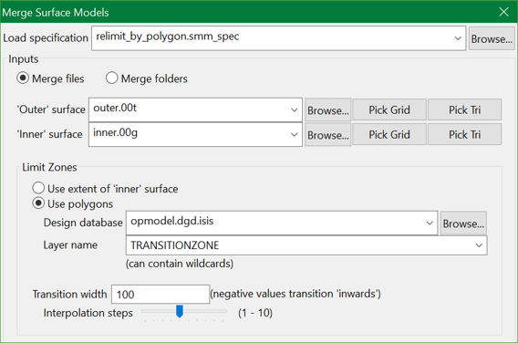
On the Model menu, click Merge Surface Models to display the following panel.
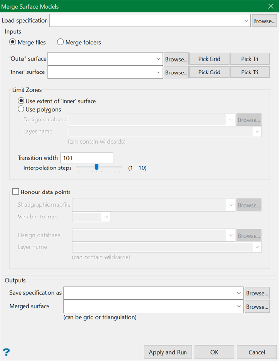
Load Specification
Specification is a pre-saved file that contains the selections for the panel elements, such as inputs, polygons, and outputs. You can choose to select a specification file from the drop-down list or browse from another location.
Inputs
Inputs are the surface models (grids or triangulations) that are to be merged. You can choose to merge two files or two folders containing multiple surfaces.
Merge files
Select this option to merge two surfaces, an 'inner' surface and an 'outer' surface. If a specification file is used, these fields are automatically populated. Optionally, you can also choose to manually select the outer and inner surfaces from the drop-down list, browse from another location, or pick from the screen.
Merge folders
Select this option to merge multiple surfaces from two folders, a folder containing 'inner' surfaces and a folder containing 'outer' surfaces. Choose the folders from the drop-down list or browse from another location.
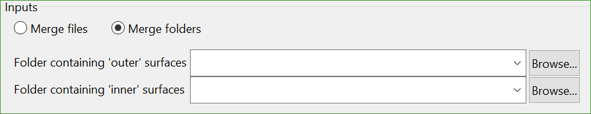
The tool merges any pair of surfaces it finds in the two folders whose filename and first two letters of the extension match, i.e. a folder of grids and a folder of triangulations can be merged as long as those aspects are matched. Example, ProjSeam.srt will match both ProjSeam.srt and ProjSeam.srg. If both the potential matches are found, the tool will use the one having the exact extension.
Limit Zones
This section allows users to select the polygon(s) for the merge. The tool uses polygon(s) to cut holes in the 'outer' surface and fill the holes with the corresponding parts of the 'inner' surface.
Use 'extent' of inner surface
Select this option to use the extent of the inner surface as the polygon to cut holes in the 'outer' surface.
Use polygons
You can choose to select polygons from a design database and corresponding layers. Select from the drop-down list or browse from another location. If a specification file is used, these parameters are automatically populated.
Transition width and Interpolation steps
To ensure that the merge is as smooth as possible, users can specify transition width and interpolation steps, over which the tool will blend between the two surfaces. By default, the transition width is 100 and interpolation steps is 5.
Note: The negative value in the transition width will blend inwards.
Outputs
Save specification as
Users can save the settings and panel elements in a specification file. Supply the filename or you can choose to overwrite an existing specification file.
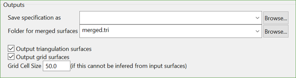
Merged surface
Provide the name for the resulting merged surface. It could either be a grid or a triangulation.
If the option Merge folders is selected at the start, then you will need to provide the folder name for the merged surface. You can also output the triangulation and grid surfaces resulting from the merge.
Example
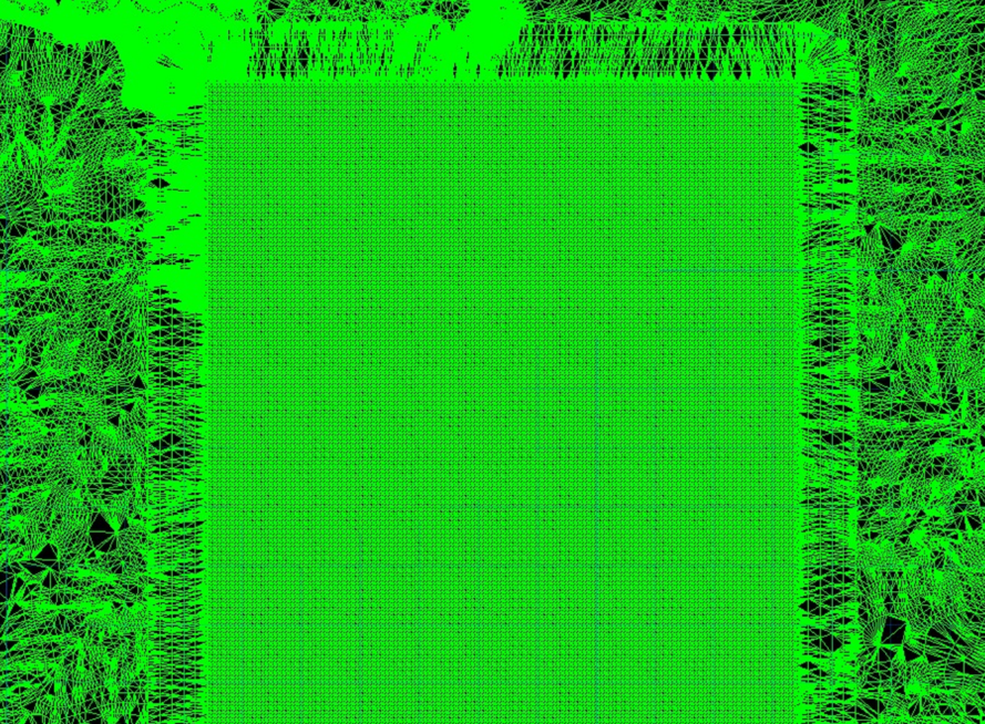
Let's take the following scenario:
Hit Apply and Run. The Vulcan Integrated Shell starts the merge process which can be seen as follows.
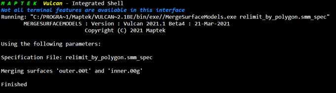
The result you see is an 'outer' triangulation merged with an 'inner' grid, together with a transition zone having a width of 100 and 5 interpolation steps.