Generate UG Drive Strings
Use this option to create survey data from triangulations. The option takes a solid triangulation of an underground drive and extracts its strings for roof (back), floor (sill), and wall (rib) positions that help generate a simplified model of the drive.
Note: Do not use stopes and other 'non-tunnel type' triangulations with this option. We also recommend that you validate the required triangulations before using the Generate option. Refer to the Model > Triangle Utility > Check option.
Instructions
- Select Survey menu
- Select UG Survey submenu
- Select Generate UG Drive Strings option
The following panel is displayed.
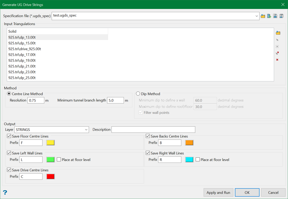
Specification file
Use the drop-down list to select the specification file if it is in the current working directory, or browse for it in another location by clicking the Browse button. A new file may also be created by typing the name of the new file in the textbox and clicking the New button.
-
 Browse
 -
 New
New -
 Save
Save -
 Save as
Note: The specification file (.ugds_spec) is used to store the parameters used in generating underground drive strings.
Input Triangulations
Select the solid triangulation(s) of the drive from which the strings (keylines) are to be generated. The triangulations can be browsed from a directory or picked up from the screen using the controls on the right.
Method
There are two methods of generating the UG drive strings:
Centre Line Method
This method uses the list of triangulations during the process and extracts a line in the geometric centre of the drive i.e. tunnel. This line is then projected to the roof, floor, and walls of the tunnel. However, the wall lines may be lowered to the floor level of the drive.
Resolution
Enter the value of the intended resolution while creating the strings. The unit is set as defined in the Vulcan Preferences. The resolution is an important factor in generating strings because the overall processing time depends on the resolution. The optimal resolution is approximately 3-4 times the width of the tunnel to process. At high resolutions, some deviations in tunnel may occur which can be termed as branches.
Minimum tunnel branch length
Enter the minimum length of the tunnel branch. The branches (generated due to the high resolution) shorter than this minimum length are suppressed eventually in the process.
In the Output section, users can choose to save and colour each strings (keylines) separately.
Dip Method
This option uses one triangulation at a time to process.
Minimum dip to define a wall
Enter the minimum vertical dip angle (decimal degrees). If the dip angle of the triangle is greater than this value, then the triangle is considered a wall triangle.
Maximum dip to define roof/floor
Enter the maximum horizontal dip angle (decimal degrees). If the dip angle of the triangle is less than this value, then the triangle is considered a roof or floor triangle.
Filter wall points
Select this check box to filter wall points. If this is check box is checked, then wall points close to horizontal sides of wall triangles will not be created.
Select OK.
Output
Layer
Enter, or select from the drop-down list, the name of the layer into which the resulting strings will be placed. The maximum size of the layer name is 40 alphanumeric characters (spaces not allowed).
Description
Enter a description to further describe the contents of this layer. The description can be up to 80 alphanumeric characters and may include spaces. If a description is not entered, then a default description will be used instead. If the chosen layer already has an assigned description, the description displays when the layer is selected. Existing layer descriptions can be overwritten.
For the Centre Line Method where multiple lines are generated, users can choose to save and colour each line separately using the available options. For Left Wall Lines and Right Wall Lines, users can choose to lower them to a floor level selecting the option Place at floor level.
Apply and Run will save the chosen parameters to the specification file and run the process to generate the output. However, OK will only save the parameters to the specification file and will not generate the output.
Hit Apply and Run button and the survey centre lines representing the floor (sill), roof (back), and wall (rib) are then generated and displayed. Although the generated data may visually appear as separate points and lines, they are all in one object per data type, For example, the roof data is all one object. The generated data, although in the layer you specified, are grouped as 'roof', 'walls' and 'floor'.
Figure 1: Generated Survey Lines
In areas of branching development and near edges, the lines that are generated may visually be broken into segments. In some cases, there will be what appears to be missing data, for example, at intersections. In other cases, instead of lines, there will be points. In most situations, these variations do not cause a problem. In a few cases there may be some minor problems, these are covered in the section on Problem Solving.
Note: Before appending new data to the generated survey centre lines, we recommend that you test the validity of what has been created by this option. Simply remove the survey triangulation and then use the Build 3D Drive option to construct a triangulation from the generated survey centre lines.
Once this triangulation has been generated, test its validity by using the Check option (under the Model > Triangle Edit submenu). If problems show up, then you may need to do some minor clean up of the data created.
