Triangulation Volumes
Use this option to calculate the cut and fill volumes for the overlapping area of two triangulated surfaces. The calculated volumes displays through the Report Window and, if desired, can also be saved in a nominated report file.
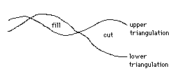
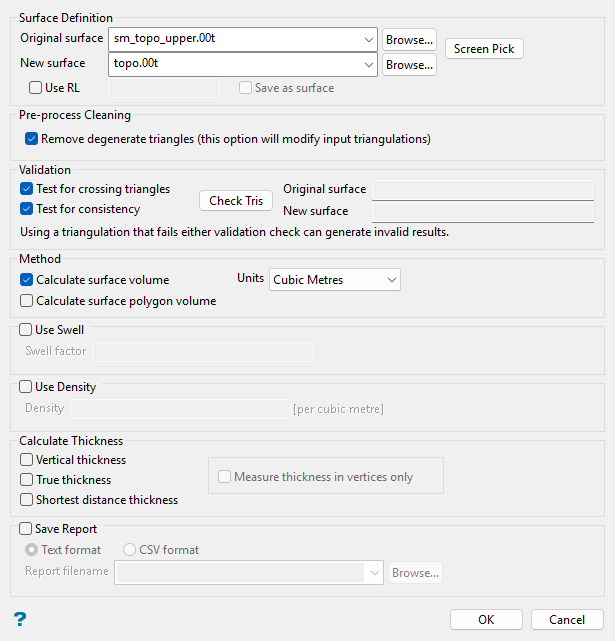
Figure 1: Cut/Fill Volume Definition
Instructions
On the Model menu, point to Triangle Surface, then click Triangulation Volumes.
Follow these steps:
-
Select the Original surface. This is the surface that represents the current (original) topography. Pick from drop-down list, which includes triangulations in the current working directory, or click Browse... to select from a different location. Alternatively, click Screen Pick to pick from triangulations current loaded on screen.
NoteCUT volume is calculated when the new triangulation surface is below the original.
FILL volume is calculated when the new triangulation surface is above the original.
Tip: The
 Invisible button, available in the Visibility toolbar, can be used to temporarily hide selected or unwanted triangulations. Vulcan's rotation tools in the Graphics toolbar, such
  Ortho Sphere Rotation and
  Virtual Sphere Rotation, can also be used to adjust your view of the loaded triangulations when using Screen Pick.
 -
Select the New surface. This is the represents the planned (new) topography. Pick from drop-down list, which includes triangulations in the current working directory, or click Browse... to select from a different location (if you did not use the Screen Pick option to pick the original and new surface previously).
Alternatively, you can select the Use RL check box to use a specified RL (reduced level, i.e. elevation) as the new surface, with the option to save the generated RL surface as a triangulation via the Save as surface check box. Note that if you elect to save the surface, you will be prompted to confirm the new triangulation name and display properties in a new panel upon clicking OK. See Model > Triangle Files > Properties... for more information on setting triangulation display properties.
-
Select the Remove degenerate triangles if you want to modify input triangulation(s) that may contain degenerate triangles to remove these features.
Note: By default, this option is enabled as it may help to reveal the issues with the surface.
NoteDegenerate triangles are those with three points along a straight line (i.e. three collinear points). They may be reported as boundaries in operations; therefore, a potentially closed triangulation will be reported as open. The pre-process cleaning step in this option removes the false boundaries.
There are two possible configurations of degenerate triangles:
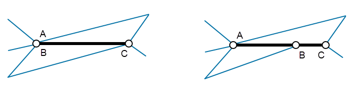
(Left) two coincident points and (Right) three points on a single line (otherwise known as a T-junction). In the diagram, the thick black lines show degenerate triangles while the thin blue ones show the other lines of the triangulation.
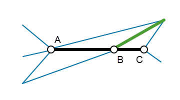
Removal of degenerate triangles may require adding triangles to the triangulation as shown in the diagram below. The green line shows the split line added to create new triangle segments.
Vulcan does not produce degenerate triangles but they may be present in triangulations imported from other packages. There are no advantages in having degenerate triangles in a triangulation; therefore, modification of the input triangulation(s) to remove degenerate triangles is justified.
-
To check the validity of the triangulations, select the desired test check boxes then click the Check Tris button. The results will be displayed in the boxes to the right of the button.
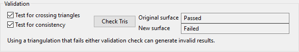
Test for crossing triangles - Select this check box to test the triangulation for self-crossing triangles.
Test for consistency - Select this check box to test the triangulation for triangle edges shared between more than two triangles.
Note: See Model Triangle Utility > Check for more information on triangulation validity checks.
-
Select Calculate surface volume to calculate the volume defined by the boundaries of the surfaces.
-
Select Calculate surface polygon volume to calculate the volume defined by the boundary of a polygon. You will need to select an existing polygon from the screen if you select this option.
-
Select the Units. This determines what units the calculation results will be given. Select from the available units in the drop-down list: Cubic Metres, Cubic Feet, Cubic Yards, Cubic Centimetres, or Acre-Feet.
-
Enter the Swell factor by which the volume has been swollen.
Note: Under normal circumstances, using this option is the wrong thing to do. You have the potential to break Newton's Law of Conservation of Mass because you will be directly affecting the bank (or unswollen) area of the block. The only time that you should use this option is if you have an in situ block that actually represents material that has already been swollen. In this case, you should set the swell factor to represent how much the block has already been swollen, which will consequently reduce the bank area back to what it should be.
-
Enter the Density factor.
-
Select Vertical thickness if you want to report the average, minimum, and maximum thickness between the original and new surface based on strict vertical measurement.
-
Select True thickness if you want to report the average, minimum, and maximum thickness measured perpendicular from triangles of the original surface to new surface.
-
Select Shortest distance thickness if you want to report the average, minimum, and maximum thickness measured perpendicular from triangles of the new surface to the original surface.
-
Select Measure thickness in vertices only to report to measuring thickness approximately only in the vertices, making the calculation faster.
-
Select Save Report to save the calculated volumes in a nominated report file in either Text format (
.txt) or CSV format (.csv). The drop-down list contains all Text or CSV files found in the current working directory. Click Browse... to select a file from another location. If an existing file is selected, the file contents will be overwritten with the new report.To create a new file, enter the file name in the text box.
-
Click OK.
The cut and fill volumes will be calculated and the results displayed through the Report Window.
