Station Section
Creates a Section View in a certain orientation and location based on a trigonometric calculation of a distance measured from a survey station. The tool will also create a grid and a drive profile template (primitive). This panel will remember the settings from the last time the tool was run.
Instructions
On the Face Mapper menu, point to Mapping, then click Station Section.
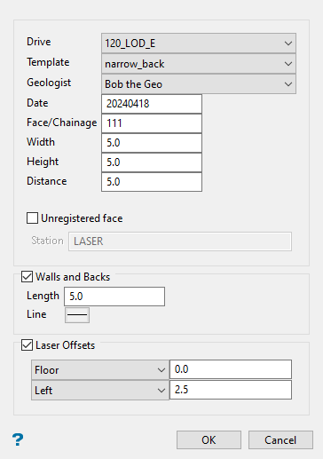
Drive
The drive in which the mapping will be completed. This is a drop-down list populated from the ‘Drive Names’ section of the Global settings.
Template
Which template is to be used to build the drive profile template. This is a drop-down list populated from the ‘Face template definition’ parameter in the Station Section settings.
Geologist
The geologist performing the mapping. This is a drop-down list populated from the global ‘Geologist’ parameter in the Usernames section of the Global settings.
Date
Todays’ date. This is automatically populated based on computer date settings.
Face/Chainage number
Which number face or chainage for the given drive is going to be mapped. A suffix, such as “A” can be added to denote a strip taken at a previously mapped face.
Width
Measured width of the face.
Height
Measured height of the face.
Distance
Measured distance from the survey station to the centre of the face.
Unregistered face
If enabled, allows a face to be mapped without having an up-to-date design file or survey stations layer. The face can be registered to the appropriate design file and survey station at a later stage using the Face Mapper > Post Processing > Register Face tool. An unregistered face will have an “_UNREGISTERED” suffix applied to the layer name in the design database. This suffix will be removed when the face is registered.
Station
The name of the survey station, or user defined reference point, from which the distance to face value was measured from – for later reference. This option will be disabled if the Laser Offsets option is selected.
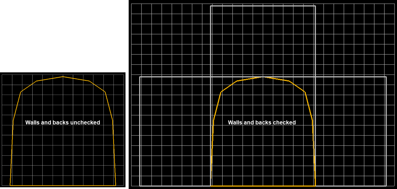
Walls and back
A checkbox to define if the user wishes to map the walls and backs with the face.
Length
The depth of the walls/backs to be mapped (i.e. the length of the cut/firing).
Line
The desired line thickness for the walls and backs bounding template boxes that will be created.
Laser Offset
Allows offset values to be defined when using a Laser as a reference for positioning a face.
Floor/Back
Allows either the floor or the backs to be used as the vertical reference point, and a “distance from floor/backs” value to be defined. When the backs option is used, the distance to backs is calculated to the vertical intersection with the mapping template at the horizontal location of the laser line on the face, not from the “height” value.
Left/Right
Allows either the left or right side of the face to be used as the horizontal reference point, and a “distance from left/right” value to be defined. This value is calculated off the horizontal distance intersection with the mapping template, not from the “width” value.
Instructions
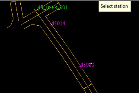
Input all relevant information into the panel and select OK. Firstly, select the survey station that was used as the reference point.
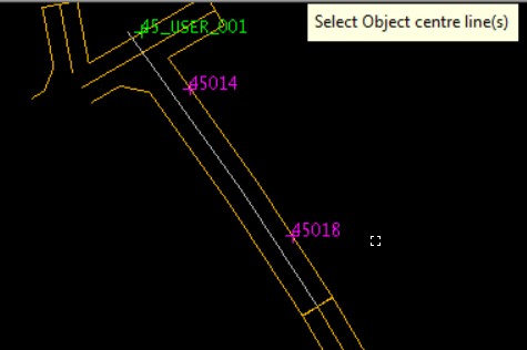
Next, select the centre line (more than one centre line may be selected, but must be selected in order such that the centre line closest to the station is selected first). Selected objects will be highlighted in grey.
Right-click twice by long-pressing on the screen (or using the RMC button on the floating toolbar) to cancel out of the object selection mode.
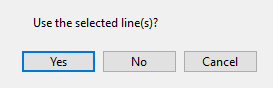
If the correct centre line(s) has been selected then press ‘Yes’ on the confirmation panel. If the wrong object has been selected by accident press ‘No’ and you will prompted to reselect your centre line(s).
Once ‘Yes’ has been selected the tool will create a section view perpendicular to the drive centre-line, create a layer with the Face ID name (created using a concatenation of the Drive and Face number fields), build a drive profile from the chosen template and width/height inputs and generate a grid at the spacing defined in the ‘spacing’ parameter in the StationSection grid settings. If Walls and backs was checked on the tool will also build rectangle boundaries for the walls and backs based on the Length input into the respective input box in the panel.