Templated Ring Design
This option allows you to automatically create ring sections and drillholes from triangulations and a reference line.
Instructions
On the Underground menu, point to Ring Design, then click Templated Ring Design.
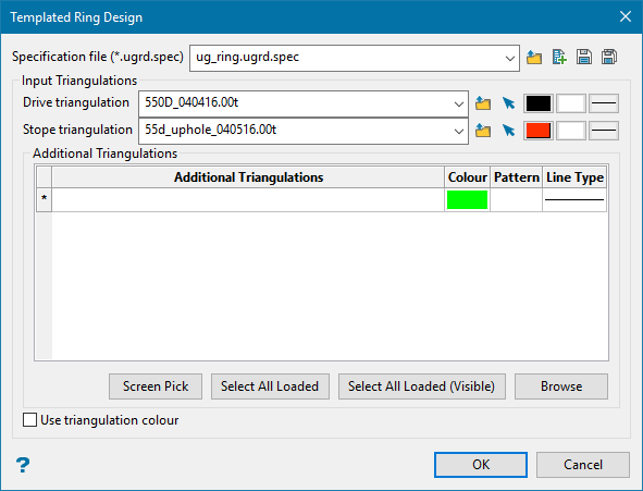
Specification file
The Templated Ring Design utility uses a (.ugrd.spec) file. Use the drop-down list to select a file from the current working directory, or browse for one in another location by clicking the Browse ![]() icon.
icon.
|
|
Browse |
|
|
New Specification File |
|
|
Save Specification File |
|
|
Save As |
Input Triangulations
Select the triangulations that will be used to create the polygons.
Note: You can also use this option to update existing polygons. To update you must select the layer that has the polygons you want to update. For enabling downstream options to use the drive and stope polygons, there can only be one polygon per ring. If the option produces more than one drive or stope polygon per ring, you will need to delete all but the one polygon you want to use for that ring.
Drive triangulation
Select the drive triangulation by choosing it from the screen or selecting from the drop-down list.
Stope triangulation
Select the stope triangulation by choosing it from the screen or selecting from the drop-down list.
Note: The colour, pattern, and line icons to customise the shapes will be disabled if the option to use triangulation colour (the checkbox found at bottom of the panel) has been checked.
Additional triangulations
Select any additional triangulations that you want to use for clipping.
Important: You must have at least a stope and drive.
Click OK to close this panel and advance to the next step.
Reference Line Selection
After shapes are picked, you will be prompted to pick a reference line if one is not found. One will be automatically selected if the Underground Open Blast Database defines a Reference Line layer and a polyline exists with a group of SRL.
Once a reference line has been selected, the next panel will be displayed, allowing you to define the rings.
Setting up the parameters for the rings can be done manually by editing the grid in the UG Interactive Blast Setup Utility Panel, or be generated automatically by clicking the Generate Rings button.
UG Interactive Blast Setup Utility Panel
UG Interactive Blast Setup Utility Panel
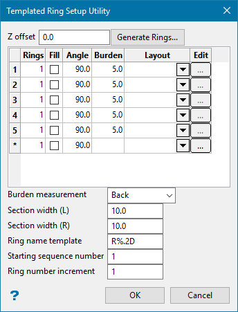
Z Offset
This defines the offset from the reference line from which the section lines will be created. It is used when drilling up into a stope above. A value of 0 will place the section lines directly on the reference line. A value of 5 will place the section lines 5 units above the reference line.
Note: The units are determined by your unit of measurement that is set up in the Preferences > Miscellaneous section of Vulcan.
Rings
This determines how many of the ring patterns to make.
Fill
Overrides the Rings value and fills the ring pattern to the end of the reference line. It will overwrite following rings, so only recommended on the last ring section.
Angle
This is the dump angle of the ring pattern.
Burden
This is the spacing between each ring section.
Layout
Layout (.ugb.spec) to use when calculating drillholes. If empty, no drillholes will be made.
Edit button
Displays the Ring Layout Information panel to allow interactive editing of the layout.
Note: This will change the values in the ugb specification file once OK is clicked on the sub panel.
Burden measurement
This defines where to measure the burden for rings.
-
Front - measures from the front of one ring to the next.
-
Center - measures from the middle of one ring to the next.
-
Back - measures from the back of one ring to the next (most common).
Section Width L/R
This defines how far the section line extends from the reference line.
Ring name template
The section lines will be named sequentially according to the prefix and sequence order. The maximum size of the prefix is 4 alphanumeric characters.
| Block Name | Result |
|---|---|
| R%.D | R1, R2, R3,... |
| R%.3DTK | R001TK, R002TK, R003TK,... |
| %.2D | 01, 02, 03,... |
Starting sequence number
Enter the starting sequence number for naming the section lines.
Section Name Template: R%.2D
Result:
Strip number increment: 2
Start Strip Number: 10
R10
R12
R14 etc
Ring number increment
This is used in the section name. Each section name will be incremented with the number specified here.
Once a ring is input, it will be drawn on screen. The initial hole will have a different colour from other holes to easier identify the inclination/start and end offsets.
Click OK.
Generate Rings Panel
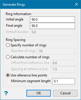
This allows the rapid generation of rings when varied angles or spacings are needed.
Rings are created with the following spacing modes, and the angles are interpreted between Initial/Final Angle.
Ring spacing
Specify number of rings
<N> rings will be generated at a constant burden spacing.
Calculate number of rings
Determines how many rings to insert with the desired spacing at the reference line within the default burden distance. This supports the use of Offset at reference line for standup ring drilling.
Use reference line points
Creates a section at each point along the reference line, forcing a minimum gap between each ring section created.
Click OK.
