Mining Solids
Use this option to quickly generate triangulation solids that can be used for scheduling and sequencing purposes.
Instructions
On the Open Pit menu, point to Scheduling Solids, then click Mining Solids.
Only four steps are needed to create the production mining solids. All other parameters allow you to customise the results.
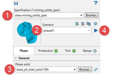
-
Enter a name for the specification file.
-
Enter a name for the scenario file.
-
Select the input solid.
-
Click the Run scenario arrow.
All the mining solids will be created and organised in assigned folders, making them convenient for scheduling and sequencing purposes.
Follow these steps:
Initial Inputs
-
Enter a name for the Specification file, then click ENTER. The file extension will be added automatically.
-
Enter a Scenario.
-
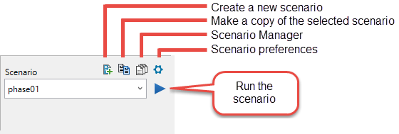
Create a new scenario - The name can be up from any number or letter combination up to 30 characters, but cannot contain special characters such as underscores, dashes, or symbols. This will create a new scenario within the current specification file. Multiple scenarios can be created for use with a single specification file.
-
Make a copy of the selected scenario - This will create a copy of the currently selected scenario, allowing you to make any changes to the parameters and saving the edits using a different name.
-
Scenario Manager - This will open the Scenario Manager panel, allowing you to copy and delete scenarios, or run multiple scenarios at the same time.
 Using the Scenario Manager
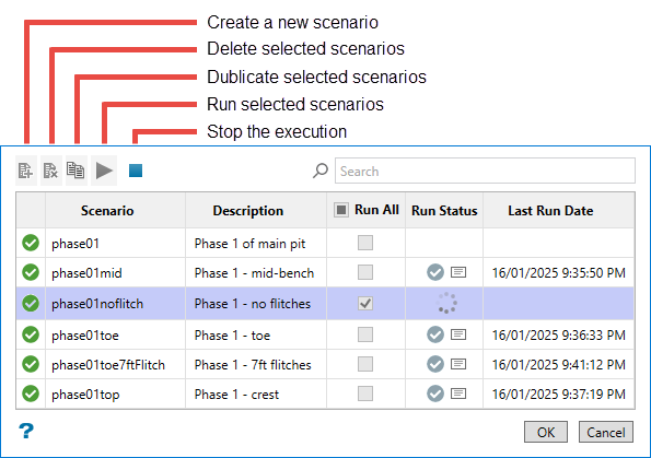
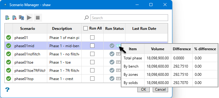
Scenario This column well list all scenarios that have been created for the current specification file. Description (optional) Double-click in a cell to enter or edit a description Run All Enable one or more checkboxes to run the scenarios. Enable the Run All option to run all scenarios listed. Run Status This will indicate if a scenario is currently being created. A checkmark will indicate that the scenario has run. You can click on the report icon to view a preliminary report.
Last Run Date This will provide the last date and time a scenario was run. -
Scenario preferences (optional) - Use this to set preferences such as mine identifiers, naming schemes, reserve parameters, attributes, filters, folders, and colours. There is also a debugging option.
Note: Setting preferences in one scenario will not influence the preferences of another scenario. Each scenario has its own set of preferences.
Editing Scenario Preferences
You can set preferences for the current project by clicking the Scenario preferences icon.
General
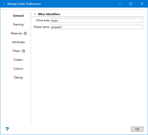
Mine area - Enter a name that will identify the mine area you are working with. By default, this will automatically be populated with the name given for the specification file.
Phase name - Enter a phase name. By default, this will be automatically populated with the name of the current scenario.
Naming
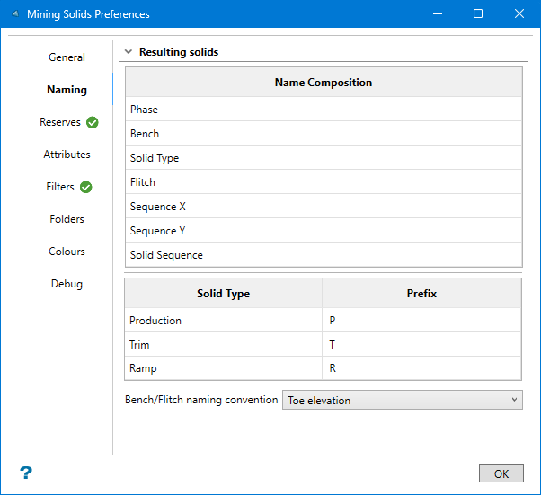
This tab shows the format used when naming each solid.
Examplephase01_160_P_F160_X04_Y03_128.00t
Note: Elevation references are based on the toe, mid-bench, or crest of the solid depending on the selection made in the Bench/Flitch naming convention option.
Phase phase01 Bench 160 Solid Type P Flitch F160 Sequence X X04 Sequence Y Y03 Solid Sequence 128 Bench/Flitch naming convention - Select between Crest elevation, Mid-bench elevation, or Toe elevation. This refers to where the elevation is measured from. The elevation is used in the name of each solid.
Reserves
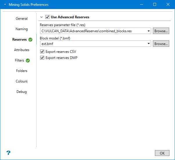
Enable Use Advanced Reserves to calculate the reserves for each mining solid.
Reserves parameter file - Select the Advanced Reserves specification file from the drop-down list, or click Browse to select a specification file using the Explorer window.
Block model - Select the block model from the drop-down list, or click Browse to select a block model using the Explorer window.
Enable Export reserves CSV to save the results of the reserve calculation as a CSV file in your current working directory. (Optional)
Enable Export reserves DMP to save the results of the reserve calculation as a ASCII DMP file in your current working directory. (Optional)
Attributes
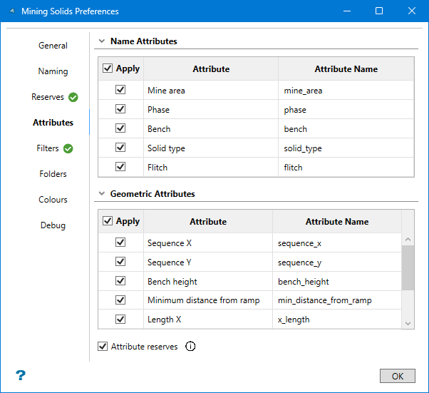
Use the checkboxes to add or remove attributes associated with your mining solids. Double-click on an Attribute Name to edit the text. Note that spaces in the names are not allowed.
Filters
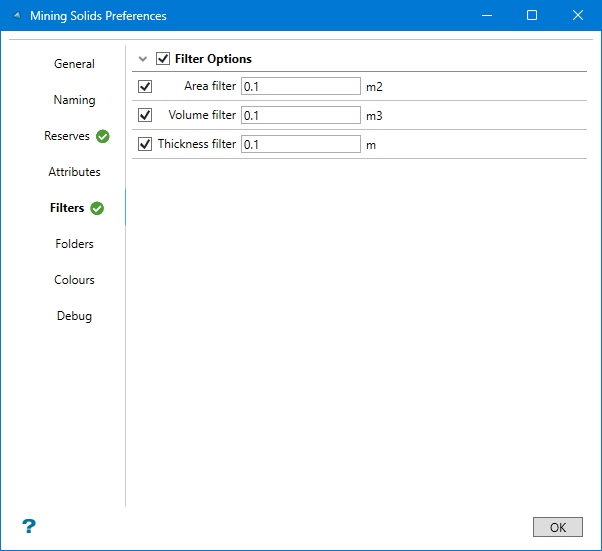
Use Filter Options to prevent the creation of solids that are too small to use. You can apply filters for the area, volume, and thickness of each resulting mining solid.
Note: If the conditions are not met, a solid will be created, but it will be stored in a special Filtered folder.
Folders
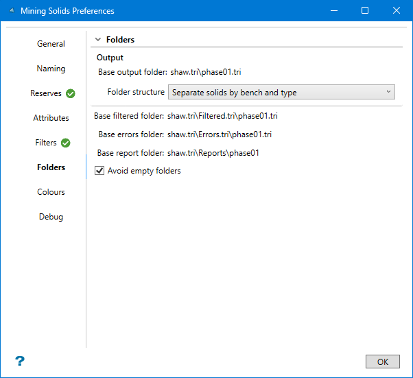
By default, the resulting mining solids are stored by bench and type, with additional folders created to hold production solids, trim solids, filtered solids, and reports. This makes it easy to work with, especially since there could be hundreds of solids created. However, you can customise the folder structure by selecting from the following options:
-
All solids in the base folder
-
Separate solids by bench
-
Separate solids by type
-
Separate solids by bench and type
Note: A base output folder is initially created and given the same name as the scenario. All additional folders are normally stored inside of this folder.
Colours
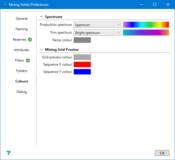
Use these options to customise the colour of the production, trim, and ramp solids. You can also customise the grid colour, and the text showing the sequence for both the X and Y directions.
Debug
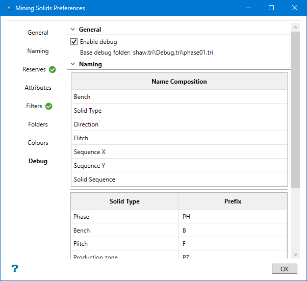
Use Enable debug for advanced troubleshooting to expose incremental cutting components if necessary. This panel shows you the naming conventions used for each type of solid. If this option is enabled, then all the triangulations used to create the mining solids will be saved and stored in the Debug.tri folder.
-
-
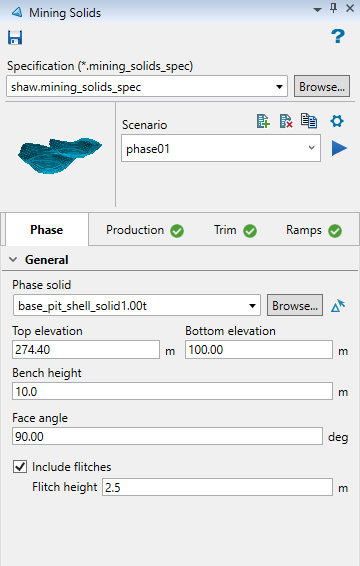
Phase tab
-
On the Phase tab, select the Phase solid from the drop-down list, or click Browse to select one using the Windows Explorer. You can also select from the triangulations loaded onto the screen by clicking the Select a triangulation icon located beside the Browse button.
-
Edit the following parameters (optional). These parameters are filled in by default, but can be customised.
Note: The units used in these parameters (metric or imperial) reflect those used in the dg1 file, not those set in Miscellaneous > Vulcan Preferences. For information about setting up or editing a dg1 file, see Getting Started > Introduction to Vulcan > Setting up Vulcan > Creating a Project File (dg1).
-
Top elevation / Bottom elevation - The elevations are automatically calculated based on the triangulation solid you selected. However, you can edit these to limit the vertical extent in which mining solids will be created.
Example: If you enter a top elevation of 200 m and a bottom elevation of 100 m, then the resulting mining solids will be within those elevation boundaries regardless of the extents of your selected input triangulation solid.
-
Bench height - Sets the height of each bench. By default, this has been set to 15 units.
-
Face angle - Sets the angle of the cutting face. By default, this has been set to vertical (90 degrees).
-
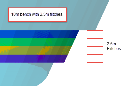
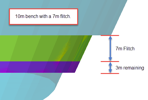
Include flitches - Enabling this option allows you to set the Flitch height. The bench will be divided by the flitch height, and a separate mining solid will be created for each flitch horizon. If only one flitch can fit within the bench, then the remaining portion will be made into a mining solid.
-
Production tab
Note: The Production,. Trim, and Ramps tabs have a status indicator checkmark to indicate if options have been enabled within the tab. A green checkmark indicates all optional inputs have been provided. A grey checkmark indicates the optional inputs are not in use. A red checkmark indicates incomplete inputs have been provided for options within the tab.
Use the Production tab to set the parameters for the Grid Layout, displaying the extent of the solid in plan view by overlaying a grid over the area. Arrows will indicate the mining direction in both the X and Y directions. You can also customise the orientation of the grid and the dimensions of the individual cells.
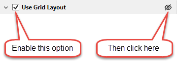
To quickly display the grid, leave the default settings on all parameters, enable the option Use Grid Layout, then click the Display a preview grid layout icon.
-
Enable the option Use Grid Layout. This enables the option to display the grid showing the extent of the solid in plan view and will allow you to edit the grid parameters.
Note: Disabling Grid Layout will create a production solid for the entire bench.
-
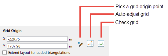
Set the Grid Origin. By default, the origin is automatically calculated and filled in for you. However, you can edit these coordinates if needed.
-
X / Y - Edit the coordinates directly here.
Note: The units used in these parameters (metric or imperial) reflect those used in the dg1 file, not those set in Miscellaneous > Vulcan Preferences. For information about setting up or editing a dg1 file, see Getting Started > Introduction to Vulcan > Setting up Vulcan > Creating a Project File (dg1).
-
Pick a grid origin point - To select the origin point from the screen, click this icon, then select the location on the screen. Note that the origin point must be in a location that will allow the grid to fully enclose the phase solid(s). After you have selected the location, a message will be displayed indicating whether or not the location is valid.
-
Auto-adjust grid - Click this to reduce the grid to the smallest possible footprint.
-
Check grid - Click this to run the grid validation. A message will be displayed indicating whether or not the location is valid.
-
Extend layout to loaded triangulations - Enable this option to include all loaded triangulation solids in your phase scenario. Use this option to maintain consistent sequencing across shared phases, or pushbacks with shared walls. This option provides a mechanism to establish a single grid origin for a mine area with multiple phases or designs.
-
-
Set the Azimuth for the orientation of the grid. By default, this is set to 90 degrees. To edit the orientation, enter the new angle directly or click the Calculate Azimuth
 icon to select a location on the screen. A line will be displayed starting from the centre of the phase solid(s) and extending to wherever your cursor is located. Right-click with your mouse when the line points in the correct direction. It does not matter how long the line is since only the angle of the line will be used in the calculation.
 You will be asked to verify the new orientation of your grid. Click Yes to complete the operation. Click No to cancel.
Tip: Editing the grid orientation will cause the origin point to shift. If the origin point is not in the correct corner of the grid, try altering the azimuth of the orientation in 90 degree increments until you get the desired results.
-
Enter the Dimensions of the grid cells in the boxes labelled Size X and Size Y. By default, these are set to 10 units.
Note: A small grid size could increase the time it takes to create all the mining solids, especially if you are using a number of large input phase solids.
Trim tab
Use this tab to define trim solids. Trim solids are used to control blasting up against the highwall in particular. These solids are typically blasted, mined, or sequenced differently than production level solids. Certain situations may not require trim solids, or may require the trim solids to be customised such as:
-
No trims are required where the bench daylights with topography
-
Trims may not be required where two phases are touching
-
Trims might not be required around ramps
To quickly create trim solids, enable the option Trim Configuration. By default, the width and length of the trim solids are set to 10 units. However, these can be customised.
-
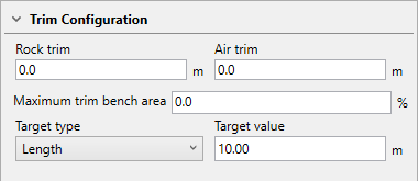
Enable the option Trim Configuration. This will allow you to edit the following parameters.
-
Enter a Rock trim width. This is the dimension of the trim perpendicular to the crest of the bench.
-
Enter an Air trim width. This is the dimension of the trim perpendicular to the toe of the bench.
-
Enter a Target value. This is the dimension of the trim solid that runs parallel to the bench crest/toe. By default, this is set to 10, but can be edited by entering a new value.
The trim solids are created at the same time as the other mining solids when the Run scenario arrow is clicked.
Ramps tab
Use this option to include ramp polygons from a selected layer when creating mining solids. This will remove the ramp areas from the production and trim zones by using the polygons to cut the mining and trim solids.
Conditions for ramp polygons:
-
Polygons should be closed and without self crossing.
-
The polygons must be positioned within the bench z-extents. For example, if a bench is from 1200 - 1190, the polygon would have to contain z-values at or within that range to be considered.
-
The polygons must be attributed with the Group = PIT$HAUL.
-
Select the Design database from the drop-down list, or Browse for it by clicking the button.
Tip: The design database does not have to be the one that is currently opened. You may select a layer from any design database.
-
Select the Layer from the drop-down list.
Generating Results
When you have completed setting your parameters, click the Run scenario arrow to create the resulting solids. All the mining solids will be created and organised in assigned folders, making them convenient for scheduling and sequencing purposes.
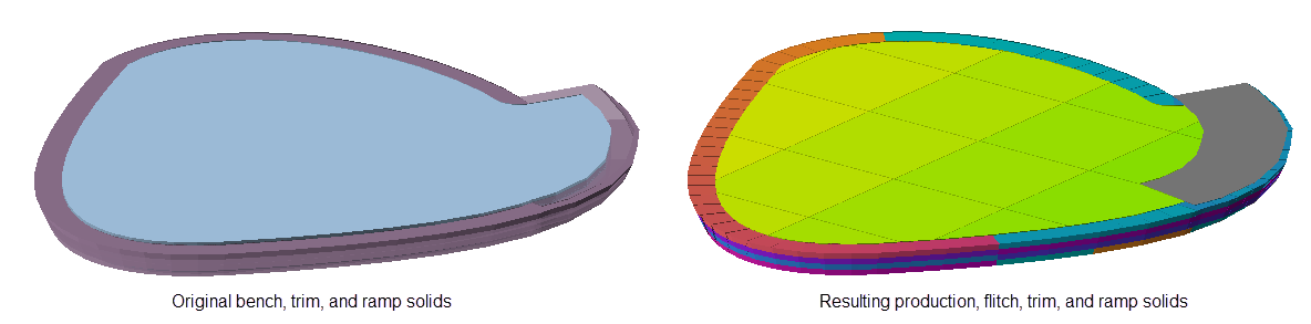
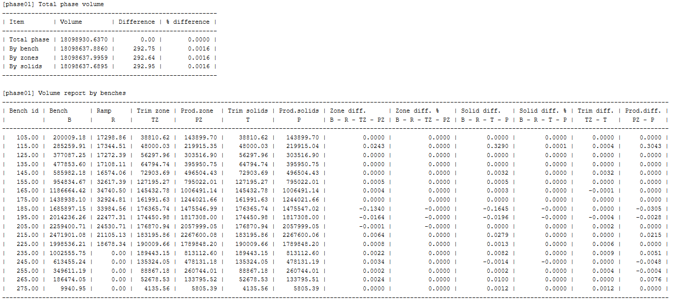
Reports
After the mining solids have been created, a report will be displayed in the Vulcan Report Window similar to that shown below. The volumes of the original solids are compared to the total volume of all the mining solids into which the original solid was divided.