Create Feature Files
The Create Feature Files tool allows the definition of the desired features for lithology polygons and structural annotation lines.
Instructions
On the Face Mapper menu, point to Setup, then click Create Feature Files.
Lithology
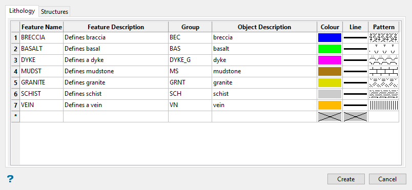
The Lithology tab on the panel allows the desired attributes to be defined for mapping lithology polygons.
Follow these steps:
-
Enter the Name of the Feature as defined in a Vulcan Feature file (
lines.ftdandpolygons.ftd). This should be the lithology name or logging code used.Note: For some clients, defining the feature name as a concatenation of domain and lithology codes can be useful, if wanting to define unique mapping units for different combinations of domain and lithology codes. For example, TQ1_SCHIST and TQ2_SCHIST could be used to distinguish between different schist units found in the TQ1 and TQ2 domains.
-
Enter the Feature Description as defined in a Vulcan Feature file. These are seen if using the Design > Create > Features.
Note: To view the lithology list, use Design > Feature Edit > Default, then selecting either
lines.ftdorpolygons.ftdas the default choice. This should ideally be set with an appropriate description for the lithology.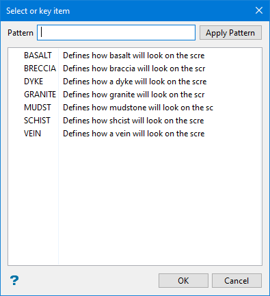
-
The Group value applied to the mapping polygon object. This can be the same as the Name and/or Object description fields if not required, otherwise different values can be used to group similar types of lithologies together by group for easily selection on screen in Vulcan.
-
The value to apply to the mapping polygon Object description field. This field allows the most flexibility for naming, as some special characters (e.g. ‘$’ or ‘-‘) can be used, as well as a mix of upper and lower case characters. This field can be utilized in some cases to best match existing logging codes.
-
The Colour that will be applied to the lines digitised using the Face Mapper > Mapping > Feature Lines tool and also the polygons generated using the Face Mapper > Mapping > Lines To Polygons tool. This can be matched to existing lithology legends.
-
The Line style that will be applied to the lines digitised using the Face Mapper > Mapping > Feature Lines tool and also the polygons generated using the Face Mapper > Mapping > Lines To Polygons tool.
-
The Pattern fill that will be applied to the polygons generated using the Face Mapper > Mapping > Lines To Polygons tool.
Structures
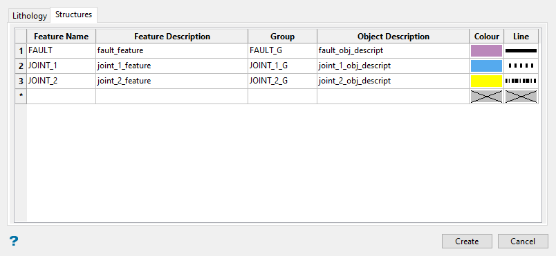
The Structures tab on the panel allows the desired attributes to be defined for structural annotation lines that can be used to sketch joint sets or fault contacts. These are separate from structures used to denote recorded structural reading (i.e. dip and dip direction), which are defined the Face Mapper > Setup > Configuration.
Follow these steps:
-
Enter the Name of the feature as defined in a Vulcan Feature file (
structures.ftd). This should be the structure name or code used. -
Enter the Feature Description as defined in a Vulcan Feature file. These are seen if using the Design > Create > Features.
Note: To view the structure list, use Design > Feature Edit > Default, then select
structure.ftdas the default choice. This should ideally be set with an appropriate description for the structure.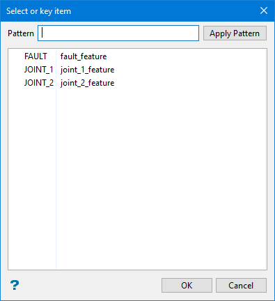
-
Enter the Group value applied to the mapping structural annotation object. This can be the same as the Name and/or Object description fields if not required, otherwise different values can be used to group similar types of structures together by group for easily selection on screen in Vulcan.
-
Enter the value to apply to the mapping structural annotation Object Description field. This field allows the most flexibility for naming, as some special characters (e.g.
$or-) can be used, as well as a mix of upper and lower case characters. This field can be utilized in some cases to best match existing logging codes. -
Enter the Colour that will be applied to the lines digitised using the Face Mapper > Mapping > Feature Structures tool. This can be matched to existing structure legends.
-
Enter the Line style that will be applied to the lines digitised using the Face Mapper > Mapping > Feature Structures tool.
-
Click Create to complete the process. When the Create button is pressed, the tool does the following:
-
Creates
lines.ftd– this contains the values defined in the Lithology tab of the panel and is applied when using the Face Mapper > Mapping > Feature Lines tool. -
Creates
polygons.ftd- this contains the values defined in the Lithology tab of the panel and is applied when using the Face Mapper > Mapping > Lines To Polygons and Face Mapper > Mapping > Feature Replace tools. -
Creates
structures.ftd– this contains the values defined in the Structures tab of the panel and is applied when using the Face Mapper > Mapping > Feature Structures tool. -
Creates
cursor.ftd– this is used by many of the tools to set the cursor snap mode as required.
-
