Split Underground Drive
Use this option to split an underground drive into four surfaces: backs, floors, walls, and faces.
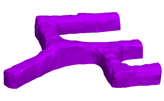
Input:

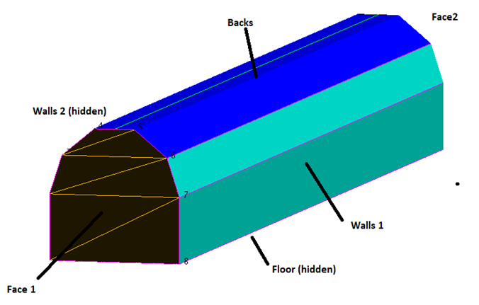
Output:
Separating solid drives into surfaces is a necessary tool for geologists and engineers as they rely more on 3D triangle solids for their underground models than strings.
These individual surfaces are key inputs for:
-
Drillhole planning - so that holes are correctly aligned in the drive
-
Face mapping - with walls and faces having surfaces to map on
-
Underground design - reverse calculating the floor, backs and face strings for design when survey has produced a solid.
Instructions
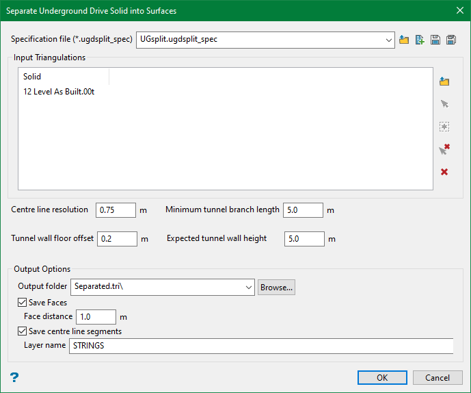
On the Model menu, point to Triangle Solid, and then click Split Underground Drive. The following panel is displayed.
Specification file
Use the drop-down list to select the specification file if it is in the current working directory, or browse for it in another location by clicking the Browse button. A new file may also be created by typing the name of the new file in the textbox and clicking the New button.
-
 Browse
 -
 New
New -
 Save
Save -
 Save as
Note: The specification file (*.ugdsplit_spec) is used to store the setup parameters for underground drive splitting.
Input Triangulations
Select the underground solids to be split. You can either browse from a directory or pick up the solids from the screen.
Note: This section will be auto populated if you are using an existing spec file.
Centre line resolution
This option defines the precision with which the centre line of the drive is calculated. The optimal resolution is around 10-20% of the drive height. Higher resolution slows down the calculation and the centre line may get fragmented introducing false branching of the drive. At lower resolution, the splitting line may become jagged and rough.
Minimum tunnel branch length
This option defines the size of the drive section that is interpreted as a branch. Otherwise, it is considered as widening of the drive.
Tunnel wall floor offset/Expected tunnel wall height
These are the parameters defining the lower and upper boundaries of the “sides” surface in the output results.
Output Options
In this section, you can define an output directory, where the results are saved to.
During the calculation, each input solid is divided into separate manifold, the shells. The names of the resulting files contain the input solid name, followed by shell number and a suffix: “backs”, floor” and “sides”. The added name parts are separated by underscores: e.g. STH_150_solid13_0_backs.00t.
Save Faces
Select this option to save the faces of the input solids. The Face distance is the length of the face surface extracted in the output.
Save centre line segments
The splitting procedure relies on calculation of the centreline of the drive. Hence, user has an option to save the centre line in the layer. If the centre line does not look right, user can manipulate resolution to improve it.
Once everything is set up, click OK to generate the output.