Simple Line
Use this option to build ramp lines with ease.
Instructions
On the Open Pit menu, point to Ramps, then click Simple Line.
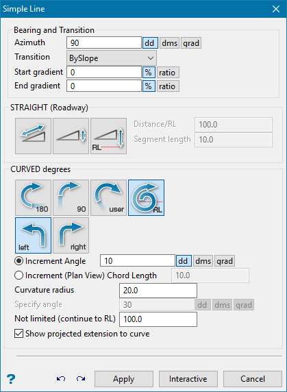
Azimuth
Enter the azimuth (as degrees). Once a line is created, the azimuth is automatically updated to follow the direction of the previous segment.
Start of gradient
The start gradient is used for the duration of the line. This is functionally equivalent to setting the start gradient and end gradient to the same value.
Constant gradient
Enter the azimuth (as degrees). Once a line is created, the azimuth is automatically updated to follow the direction of the previous segment.
End gradient
The gradient of the line is interpolated from the start gradient value to this end gradient value.
STRAIGHT (Roadway)
Select this option to create a straight ramp. You will need to specify the distance (the unit of measurement is set in the .dg1 file). The distance can be defined through one of three methods:
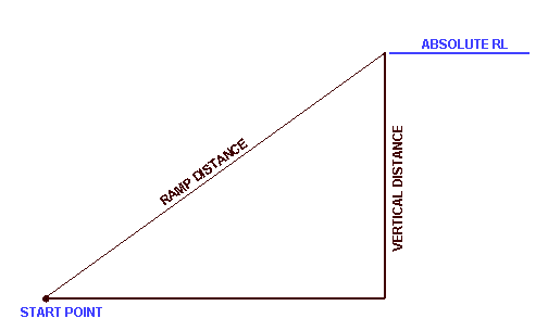
Figure 1: Roadway Distance
|
|
Ramp - Distance defined along Roadway. This is the ramp distance, measured along the specified gradient, along the roadway. |
|
|
Vertical - Distance defined by Relative Elevation. The roadway will extend along the specified gradient until the vertical distance (elevation gain/loss) has been attained. |
|
|
RL - Distance defined to Absolute Elevation. The roadway will extend along the specified gradient until the absolute elevation (RL) has been attained. |


Note: A warning message appears if a roadway at the specified gradient will not reach this RL.
CURVED DEGREES
|
|
180° - Defines a half turn. |
|
|
90° - Defines a quarter turn |
|
|
User - Defines a user specified turn. |
|
|
RL - Defines a turn limited by RL. |
|
|
Right - Defines a turn as a right turn. |
|
|
Left - Defines a turn as a left turn. |


Increment Angle
Select this option to specify an increment angle. The increment angle determines how many chords are required to make up the curve. The angle is entered in degrees. Instead of an increment angle you can specify an increment chord length (see next field).
Increment (Plan View) Chord Length
Select this option to specify the (Plan view) length of each chord making up the curve. This means that for a gradient of 1:10 and a chord length of 10m, there will be a 1m difference in elevation between each point on the curve.
Curvature radius
The default radius, which can be overwritten, is derived from the Underground Development preferences file (UGDEV.prefs). This file is created through using the Set Up option.
Specify angle
The angle of sweep (curve) may be defined as Full, Three quarter, Half, Quarter, a specified angle or as not limited.
Not limited (continue to RL)
The angle of sweep (curve) may be defined as Full, Three quarter, Half, Quarter, a specified angle or as not limited. In the latter case the angle continues to the RL.
Show projected extension to curve
Select this check box to show the projected straight line extension to the curve.
Apply
Apply the line and continue designing.
Interactive
Remain in the Centre Line Panel and use interactive edit commands without clicking out of the function. Once the interactive edit is made, select Apply and continue designing in the panel.
Cancel
Close the panel and return to the Create/Append prompt.
