Remove by Location
Use this option to remove triangulations from particular areas of the screen. You can define the region of interest by selecting an existing triangulation, entering coordinates, or digitising a rectangle, then remove triangulations from inside or outside of this region. It is also possible to remove triangulations that are partially inside or outside of the region.
Note: Before using this option, the required triangulations need to be loaded onto the screen.
Instructions
On the Model menu, point to Triangle Files, then click Remove by Location....
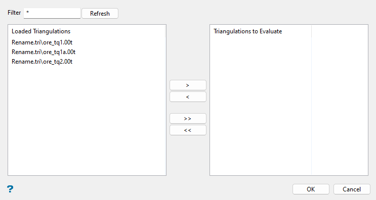
Use this panel to nominate triangulations to be considered for removal before defining the region that will ultimately be used to remove the subject triangulations.
Follow these steps:
-
Select triangulations to be considered for removal by selecting from the Loaded Triangulations list and moving to the Triangulations to Evaluate list.
To highlight multiple list items at once, use the left mouse option in combination with the Shiftkey (this is for items that are adjacent in the list; for non-adjacent items, use the Ctrlkey and the left mouse option).
Tip: To filter file names in the list, enter text in the Filter field and click Refresh. Wildcards (
*> for a multi-character and?> for a single-character wildcard) may be used in the entry.Move the items to the selection list on the right side of the panel.
- Click the
 button to move the highlighted items to the selection list on the right.
 - Click the
 button to remove the highlighted items from the selection list on the right.
 - Click the
 button to move all items to the selection list on the right.
 - Click the
 button to remove all items from the selection list on the right.
- Click the
-
Click OK to advance to the next panel and define the region that will be used to remove subject triangulations.
-
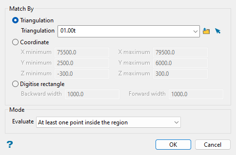
Select from the following methods to define the region to match triangulation locations to and filter the previously selected triangulations to remove:
-
Triangulation: Select this option to choose an existing triangulation that will define the region. Select from the Triangulation drop-down list, which includes all triangulation files in the current working directory, or click
 Browse to select from another location. You may also select from triangulations that are currently loaded on-screen with the
  Screen Pick option.
 -
Coordinate: Select this option to manually specify the minimum and maximum X, Y, and Z coordinates of a 3D box to define the region.
-
Digitise rectangle: Use this option to digitise a rubber-band rectangle on the screen, with a specified thickness, that will be used to set the minimum and maximum X, Y, and Z coordinates of a 3D box to define the region. After completing this panel and clicking OK you will be prompted to pick the lower left corner then the upper right corner of the rectangle in the Vulcan workspace.
Note: Depending on your orientation in the Vulcan workspace when you select this option, you will need to specify either the Z minimum and Z maximum or the Backward width and Forward width to define the total thickness of the rectangle that you will digitise.
If the Vulcan workspace was in plan view when you selected the Remove by Location... option, you will need to enter values for the following fields in the Digitise rectangle method to define the region. The default values for these fields are the minimum and maximum elevation defined in the project specification file (
.dg1).-
Z minimum: Enter the lowest elevation to be used to select the triangulations.
-
Z maximum: Enter the highest elevation that will be used to select the triangulations.
If the Vulcan workspace was in a rotated view (i.e. not plan view) when you selected the Remove by Location... option, you will need to enter values for the following fields in the Digitise rectangle method to define the region. The default values for these fields are the dimension of the Vulcan screen.
-
Backward width: Enter the distance, in real world coordinates, behind the plane defined by the rubber-band rectangle (i.e. into the screen) to be used to select the triangulations.
-
Forward width: Enter the distance, in real world coordinates, in front of the plane defined by the rubber-band rectangle to be used to select the triangulations.
-
-
-
Specify the mode in which to filter selected triangulations to remove with respect to the defined region. Select from the following modes available in the Evaluate drop-down list:
-
Triangulations fully inside the region: Select this option to remove only triangulations that are completely inside the region.
-
Triangulations fully outside the region: Select this option to remove only triangulations that are completely outside the region.
-
At least one point inside the region: Select this option to remove triangulations that have at least one point inside the region.
-
At least one point outside the region: Select this option to remove triangulations that have at least one point outside the region.
-
-
Click OK to remove triangulations that match your defined criteria.
Note: If no triangulations are located that match the defined criteria, a warning message displays and no triangulations are removed. If this occurs, check that triangulations do exist in the specified directory and that the defined 3D region is appropriate.
