Clip by Multi-Poly
Use this option to clip strings against the edge of polygons.
Instructions
Note: All the polygons that you want to clip must already loaded into the screen prior to using this option. Also, load the polygon(s) that you want to use as the clipping boundaries.
On the Design menu, point to Object Edit, then click Clip by Multi-Poly.
Follow these steps.
-
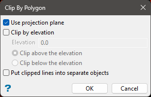
In the Clip By Polygon panel, select which options you want.
Use projection plane - Select this if you want to use a projection plane other than plan view. The Projection Plane panel will be displayed that allows you to define the viewing plane.
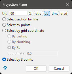
Dip - The dip is the angle of the section from horizontal. Valid dip angles are between -90° and 90°.
Select section by line - Select this option to define the plane by selecting an existing line and specifying the dip. Only design strings may be picked and it is not possible to pick a line in an underlay. The direction of the view, and therefore the direction of the stepping, depends on the digitised sequence of the line. The digitised sequence of the line can be reversed using the Reverse option (under the Design > Object Edit submenu).
Select by points - Select this option to define the plane by digitising two points and specifying the dip. To locate a point precisely, use the Snap to Objects or Snap to Points modes (on the Digitise toolbar). Points may be snapped onto underlays, such as block model slices or triangulations. If you use Indicate mode to select the points, then the points have the current default Z value.
Select by grid coordinate - Select this option to define the plane by using a specific grid co-ordinate. The grid co-ordinates can contain up to three decimal places. To achieve the best results for the following three methods, we recommend using the Zoom Data Extents icon (on the Graphics toolbar) in order to view all of the graphics.
By Easting - Select this option to enter a specific Easting value (X value).
By Northing - Select this option to enter a specific Northing value (Y value).
By RL - Select this option to enter a specific RL value (Z value).
Select by 3 points - Select this option to define the plane by digitising 3 points. To locate a point precisely, use the Snap to Objects or Snap to Points modes (on the Digitise toolbar). Points may be snapped onto underlays, such as block model slices or triangulations.
Clip by elevation - Select if you want to limit the objects being clipped by elevation. Enter the elevation, then select whether you want the object(s) clipped above or below the elevation.
Put clipped lines into separate objects - Select this option to create separate objects from the segments of the polygons that would otherwise be deleted.
-
Select OK to close the panel and select objects.
-
Select the polygons that you want to use as clipping boundaries. You will be prompt whether you want to clip the portion that is inside or outside of the clipping polygon. When you have completed your selection, right-click to continue.
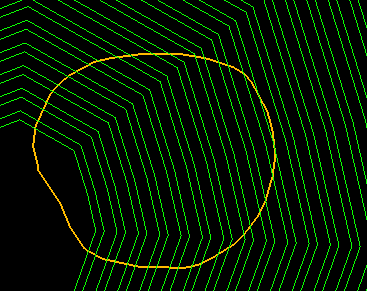
Figure 1: The green polygons are the bench polygons that we want to clip. The orange polygon is the polygon we are using to define the border of our clipping zone.
-
Select the objects that you want to clip. After you have made your selection, right-click to complete the operation.
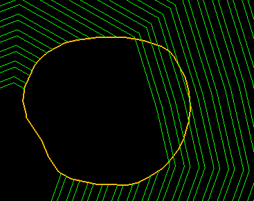
Figure 2: All polygons inside the clipping polygon and below the elevation of 100 feet have been clipped.
-
If you are satisfied with your results, be sure to save the layers.
If you are not satisfied, click the Undo arrow to reverse the process.
