Daylight Windows
Create Daylight Windows
The Daylight Windows option to create daylight and toppling windows, as well as friction cones for display on a stereonet. These windows are used to determine possible pit wall failure due to structural deficiencies. Structures that can be particularly problematic include those whose orientations are similar to that of the pit wall. The terms daylight, topple and friction cones are explained below.
Firstly, the Daylight Window option is used to see any of the structures in the walls of the pit that might slide out. Secondly, friction cones are used to determine if they may slide out. After this, you need to determine whether the structure will topple out, using the Toppling Window option.
Daylight
Daylight structures are structures that protrude, or can protrude out into free space away from the pit wall, because a block of rock has slid or can slide along an inclined weakness. The steeper the pit wall, the more chances there are for daylighting structures. Use the Daylight Window option to determine whether you are going to potentially see any of the structures in the wall(s) of your pit that might slide out. Structures that slope back into the solid rock are not classed as daylighting.
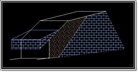
Figure 1: Daylight Block
A daylight window displays as a circular area on the stereonet to help define a structure that is likely to daylight. Structures displayed outside the daylight window are not likely to fail. Diagram 4 shows a daylight window projection on the stereonet. The dip is 50° and dip direction is 90°. The window is projected from the centre point of the stereonet to the pole point of the structure. The circle displayed is of the same diameter as the distance from the centre of the projection net to the pole point.
The daylight window is a useful method of identifying kinematically possible failure modes. This window is the locus of all the poles representing planes whose dip directions lie in the plane of the slope face, and therefore daylight in the slope.
The lower the dip angle, the smaller the daylight window; the higher the dip angle, the greater the daylight window. Thus, the higher the dip angle of the inclined plane, the more structures will, potentially, daylight on the inclined plane.
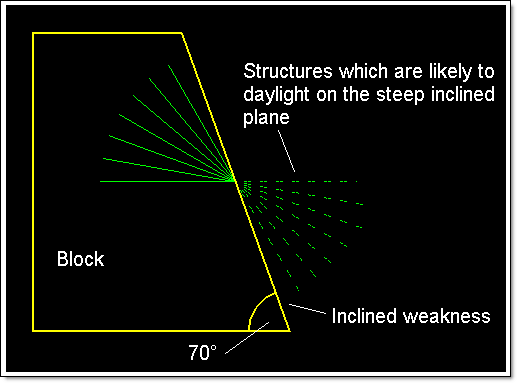
Figure 2: Higher Dip Angle of the Inclined Weakness
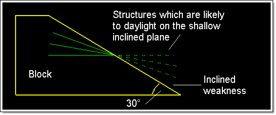
Figure 3: Lower Dip Angle of the Inclined Weakness
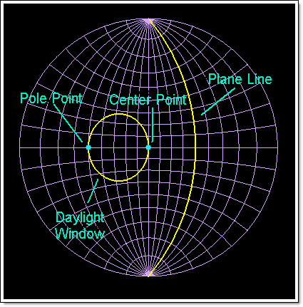
Figure 4: Stereonet Projection of a Daylight Window
Topple
A topple occurs when a load of rock that is inclined steeply into the pit wall or hillside overturns. It is called toppling because the rock falls from the crest, not the toe of the rock formation (Diagram 5).
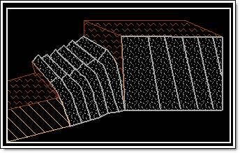
Figure 5: Toppling Block
A block has greater potential to topple or pivot out at pit wall or hillside when it is steeply inclined into the wall or hill.
A toppling window displays as a polygonal area on the stereonet to help define a structure that is likely to topple. Diagram 6 shows a toppling window projection on the stereonet. The dip is 60°, dip direction is 130°, angle of inclination is 10°, and friction angle (ø) is 30°. The window is projected from ø away from the plane line to the edge of the stereonet and given a width of 10° (the angle of inclination).
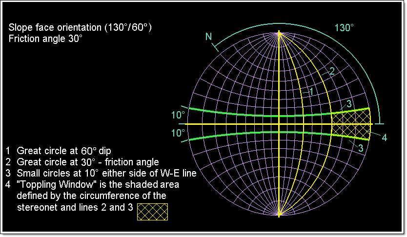
Figure 6: Stereonet Projection of Toppling Window
Friction Cone
Friction between rock surfaces can be represented on a stereonet by small circles in the projection. If the resultant of all forces acting on the block is inclined with the normal at an angle smaller than the friction angle (ø), then the block will remain where it is. This in turn allows you to calculate that the allowable resultant forces is a cone of vertex 2ø (twice the friction angle).
Using this cone, it is possible to project onto the stereonet, a small circle around the centre of the projection net with a radius of ø. Diagram 7 shows a friction cone projection on the stereonet. The friction angle ø of 35° is used as the radius for the circle (locus of cone), projected from the centre point of the stereonet.
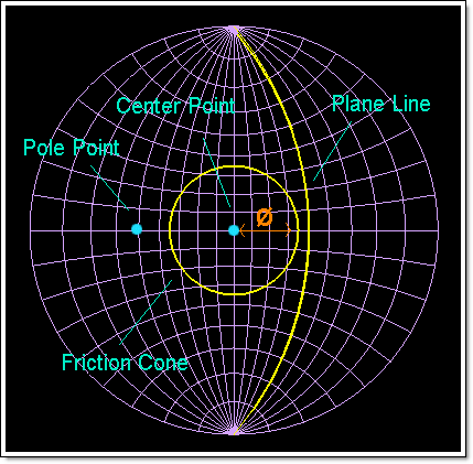
Figure 7: Stereonet Projection of Friction Cone
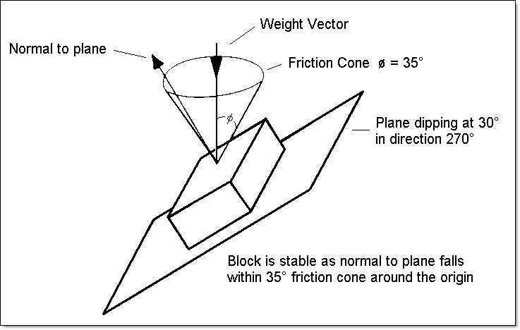
Figure 8: Friction Cone in Relation to Block on an Inclined Plane
Instructions
- Select Geotech menu
- Select Analysis submenu
- Select Daylight Windows option
The following panel displays.
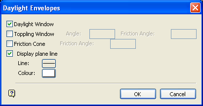
Daylight Envelopes panel
Daylight Window
Select this check box to create a daylight window on the stereonet projection.
Toppling Window
Select this check box to create a toppling window on the stereonet projection. You will need to specify both the slope's angle of inclination, and the friction angle of the rock. The friction angle applies to either side of the slope that you want to consider as being liable to topple.
Friction Cone
Select this check box to create a friction cone on the stereonet projection. You will need to specify the friction angle that will be used as a radius to create a circle from the centre of the projection net.
Display plane line
Select this check box to display the plane line on the stereonet projection.
Note: If you have previously created the plane line (great circle) of the pit wall and the pole to this plane (using the Create option), then you may not need to check this check box. However, we recommend to check it as a check on your work when entering the dip and dip direction later in this option.
Line
Select the line type for the display. This is selected from a list of line types delivered with Vulcan.
Colour
Select the colour for the display. The colour is selected from the current colour table.
Select OK.
Once selected, you will need to digitise the point representing the pole of the pit wall plane. Once a point has been indicated, you will need to confirm its position. The Retain option accepts the digitised point, and the Edit position option to edit the position of the point through the following panel.
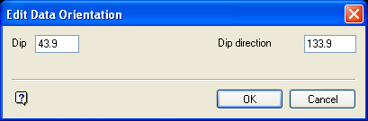
Edit Data Orientation panel
Dip/Dip direction
Enter the new dip and/or dip direction values for the point.
Note: These values are for the pole to the pit plane, NOT the dip/dip direction of the pit plane itself.
Select OK.
The digitised point is created and the windows and cones are displayed.
On the stereonet you will see the great circle representing the pit wall strike and dip (created by ticking the Display plane line check box and/or using the Create option), and you will see a circular area representing the area containing poles to the structural planes whose dip directions lie in the plane of the pit wall slope, and therefore daylight. All of these structures are possible sources of pit wall failure (see Diagram 4).
Any structure whose pole lies outside the small circle friction cone has the ability to move, it is at an angle or inclination greater than that of the friction angle of the rock. However, only those poles that also lie inside the daylight window are inclined in a direction such that they are able to slide out. In other words, the structures that can slide out have a dip direction in the same general direction as the pit wall in question.
Any structure whose pole lies in the polygon (i.e. friction angle) may topple. Structures whose poles lie beyond this window, along the great circle, are not parallel enough to the slope in question to topple. Structures whose poles lie between the toppling window and the centre of the stereonet are too flat to topple.
Data created in the Daylight Window option is removed through the Design > Object Edit > Delete option.
