Create Section
Generate Lines of Cross Section
The Create Section option offers you five methods for generating section lines. Section lines are required for profile generation and thus for volume calculation. They should be placed and spaced in such a way as to produce the best end area volume.
Instructions
- Select Survey menu
- Select Survey Volumes submenu
- Select Create Section option
When the option is selected you are prompted to select a method to create section lines.
Each method is described in detail on the following pages. For your convenience, a new page is started for each method.
Parallel
Perpendicular
X axis
Y axis
Single
Parallel
The Parallel method of generating section lines requires you to define a baseline (by indicating two points) against which parallel section lines are created. A third point determines the extent of the section lines.
Figure 1: Parallel method
Selection of the Parallel method produces the following panel.
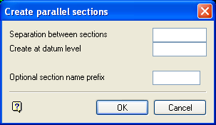
Create parallel sections panel
Separation between sections
This is the distance between the parallel cross sections.
Create at datum level
The sections are generated at the nominated datum level. If not specified, the default Z value is used.
Optional section name prefix
This can be used for a set of section lines, For example, if prefix A was used for the six section lines in Diagram 1, they would be named A1 to A6.
Select OK
To accept the panel:
Indicate the location of one end of the first section line. Any of the design entry modes can be used.
-
Indicate the other end of the section line. Again, any of the design entry modes can be used.
-
Indicate the extent of the area to be section
-
Depending on the separation entered in the panel, the appropriate number of equally spaced cross section lines are then generated.
Perpendicular
The Perpendicular method of generating section lines requires you to define an alignment line by indicating two points. The section lines are created perpendicular to this line as shown in Diagram 2.
Figure 2: Perpendicular method
Indicate the first point of the alignment line. Any of the design entry modes can be used.
Indicate the other end of the alignment line. Again, any of the design entry modes can be used. The last section line created will coincide with the point indicated here, regardless of whether the 'separation' divides equally into the distance selected or not (see Diagram 2). The following panel is then displayed.
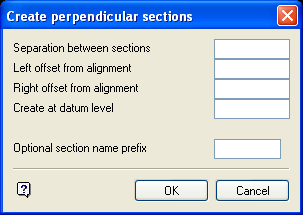
Create perpendicular sections panel
Separation between sections
This is the distance between the parallel cross sections.
Section name prefix (optional)
This can be used for a set of section lines, For example, if prefix A was used for the seven section lines in Diagram 2, they would be named A1 to A7.
Left/Right Offset from alignment
This is the extent of the section line from the alignment line. The orientation ('left' or 'right') of the offset is determined by "looking" from the first digitised point of the alignment line to the second point as illustrated in Diagram 2.
Create at datum level
The sections are generated at the nominated datum level. If not specified, the default Z value is used.
Optional section name prefix
This can be used for a set of section lines, For example, if prefix A was used for the six section lines in Diagram 1, they would be named A1 to A6.
Select OK.
To accept the panel. The section lines are generated.
X Axis
The X Axis method to generate equally spaced vertical section lines at a nominated interval across the area of a selected layer as illustrated in Diagram 3.
Figure 3: X Axis Method
Select the survey or design layer over which section lines are to be generated. Once indicated, the string is highlighted and you are prompted to confirm your selection. After confirming the selection of the layer, the following panel displays.
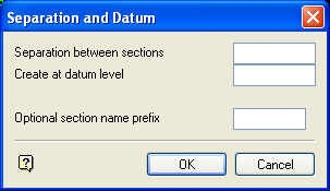
Separation and Datrum panel
Separation between sections
This is the distance between the parallel cross sections.
Create at datum level
The sections are generated at the nominated datum level. If not specified, the default Z value is used.
Optional section name prefix
This can be used for a set of section lines, For example, if prefix A was used for the six section lines in Diagram 3, they would be named A1 to A6.
Select OK
To accept the panel. The section lines are generated. If the area does not divide equally by the nominated separation, an extra section is inserted to coincide with the end of the area, ensuring that the full extent of the layer is covered.
Y Axis
The Y Axis method to generate equally spaced horizontal section lines at a nominated interval across the area of a selected layer as illustrated in Diagram 4.
Figure 4: Y Axis Method
See the X Axis method for a description of this option as the only difference is that one generates horizontal section lines and the other generates vertical lines. Once the section lines have been generated, you are returned to the Survey Volumes menu.
Single
The Single method to generate a single section line at a nominated interval and nominated position across the selected layer.
When the option is selected, the following panel displays.
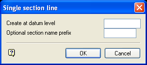
Single section line panel
Create at datum level
The section is generated at the nominated datum level. If not specified, the default Z value is used.
Optional section name prefix
This can be used for a set of section lines, For example, if prefix A was used for the six section lines in Diagram 1, they would be named A1 to A6.
Select OK
To accept the panel:
Indicate the first point of the alignment line. Any of the design entry modes can be used.
Again, any of the design entry modes can be used. Once indicated, a line is generated between the nominated points.
