Backs Mapping
Creates a mapping template from survey pickup strings and creates a section view to allow the plan-view mapping of underground geological information in the backs (roof of the drive). Also creates incremented measurements away from a given reference point.
Instructions
On the Face Mapper menu, point to Mapping, then click Backs Mapping.
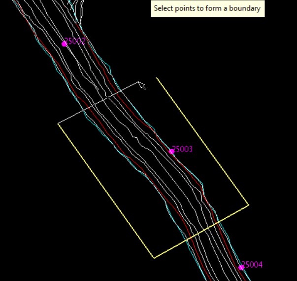
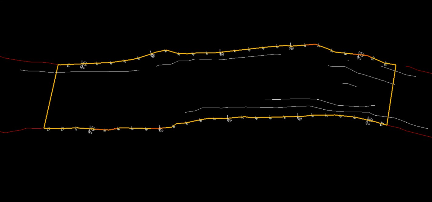
When running the Backs Mapping tool the user will first be prompted to interactively digitise a 4-point polygon (in plan view) that defines the boundary of the region that will be used to build the mapping template. Digitising 4 points is import to ensure the mapping template is created as expected.
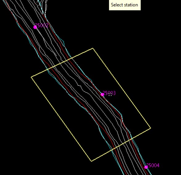
Once a bounding polygon has been the user is prompted to select a survey station (or user defined reference point) – this will be used as the reference point from which measurement marks will be calculated and created.
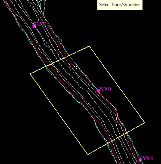
After selecting the survey station the user is prompted to select the floor or shoulder string from which they wish to use to define the mapping template.
Once the floor or shoulder string has been selected the user will be prompted to digitse the first back point (i.e. the furthest point backwards from the survey station) on the selected floor/shoulder string, followed by the first forward point (i.e. the furthest point forwards from the survey station) on the same side of the selected string as the first back point.
The user will then be prompted to digitse the second forward point on the opposite side of the drive to the first two points, followed by the second back point. These points are used to define the extent of the reference measurement marks that get created on the mapping template. These points are optional, and the tool will run if only 1 set of forward and back points selected on the same side of the drive as the survey station.
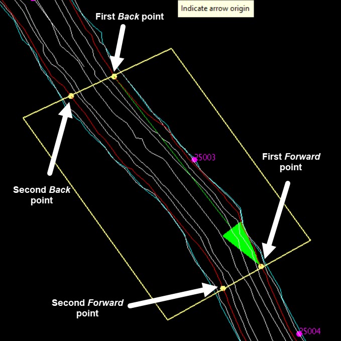
Once the four points have been digitised the Backs Mapping panel will be displayed, along with a large green arrow indicating the direction from Back to Forward points.
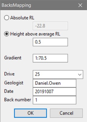
Absolute RL
The average RL value calculated from the selected shoulder/floor string.
Height above average RL
A height can be entered to create the mapping template projected to the height above the calculated ‘Absolute RL’. i.e. entering 0.5 will create the mapping template 0.5 units above the calculated Absolute RL.
Gradient
The calculated average gradient of the drive in the region to be mapped – this defines the orientation the mapping template will be created in and the section view created from it. The calculated value can be overwritten by the user if a more desirable gradient is preferred.
Drive
The drive in which the mapping will be completed. This is a drop-down list populated from the corresponding settings in the FaceMappingConfig.xml file.
Geologist
The geologist performing the mapping. This is automatically populated based on the users’ login details.
Date
Todays’ date. This is automatically populated based on computer date settings.
Back number
Which number backs map for the given drive is going to be mapped.
Once the panel inputs are finalized and ‘OK’ is selected the tool creates a mapping template, creates a 3-point section view from the template, rotates the view to align longways across the screen and creates incremented measurements away from the selected station.
As per face mapping, FeatureLines can be used to digitise lith boundaries, followed by LinesToPolygons to build mapping polygons. After this the AssignAttributes tool must be run to assign reference information to each of the polygons.
