Create Survey Triangulation
Create Triangulations from Survey Data
Use the Create Survey Triangulation tool to generate a solid model of a drive based on underground survey data. This function takes centre lines (strings) that define the floor (sill), roof (back) and wall (rib) surfaces to create 3D drives which model breakouts in these surfaces. Its function is similar to that of the Triangle Utility found under Model > Triangle Utility.
Requirements:
- Drive measurement strings are supplied as design database objects.
- Each string is assigned a Group name to identify its position in the object, For example, Back.
- Spot height strings should have different names from Floor, Back and Wall objects.
- Each wall string requires a different group name, For example, Wall1, Wall2.
- Each string in the Floor, Back and Wall Breakout groups must be closed.
- Spot height strings do not require closure.
- Multiple wall strings are allowed as long as they do not intersect with each other.
- Objects with complex topology (multiple connections) such as pillars must be separated into simple, single-connected objects before processing.
If your drive does not contain a multi-connected object, go to Open to begin using the Create Survey Triangulation tool. Otherwise, follow the instructions below. The instructions are for a pillar object, but can be used for other complex objects.
Preparing a Pillar Object for the Create Survey Triangulation Tool
The Create Survey Triangulation function requires that an object describes a single-connected drive. For this reason, all pillar objects in a multi-connected drive must be separated into individual objects before running this function. Follow these steps to divide a multi-connected object into multiple single-connected objects for processing by the Create Survey Triangulation tool.
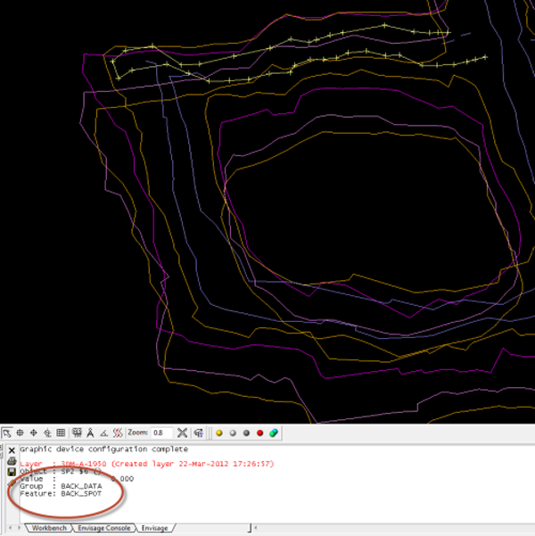
- For a pillar object, identify the line group with the most spot height lines. To identify which group a line belongs to, click Design > Layer > Identify. In this example, the Back group contains the most spot height lines.
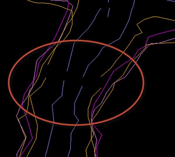
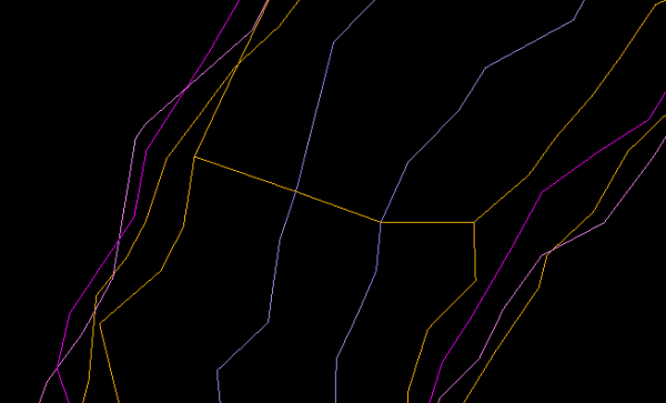
- Identify an area where the lines in this group run close to each other and then at this point split each line in this group. To split a line, click Design > Object Edit > Split:Split by Point and follow the on-screen instructions. The example below shows all Back strings split.
- Close the ends of the split strings in the main drive object. Enable Snap to Points and use Design > Point Edit > Append to append a line which connects end points up to but not including the last string in this line group.
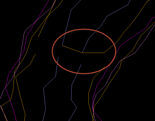
- Use Design > Object Edit > Join Lines to close the boundary of the main drive object, as shown below.
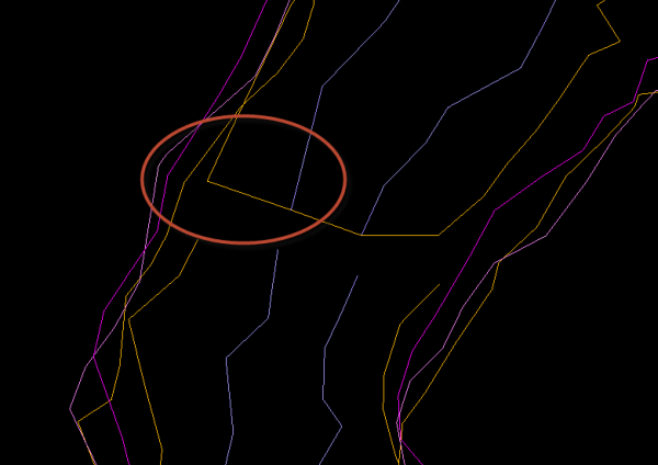
- Lines in the pillar object also need closing. Use Design > Point Edit > Append to connect end points of the pillar object lines with the corresponding end points of the now closed main drive object.
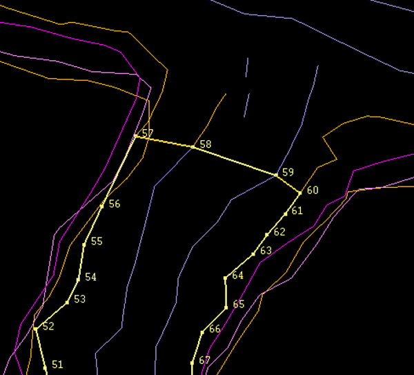
- Use Design > Point Edit > Append to append a line which connects end points up to but not including the last string in this pillar line group. The appended line for the pillar object exactly matches the line previously appended to the main drive object. Similarly, use Design > Object Edit > Join Lines to close the boundary of this object, exactly matching the boundary to the main drive object. In the example shown below, the end points of the pillar object were connected by appending a line from point 57 to 59, and then joining points 59 and 60.
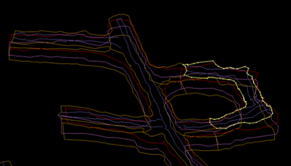
- At another point in the pillar object, for both the pillar object and the main drive object, repeat the splitting and closing procedure described in steps 1-6. This time, instead of using Design > Object Edit > Join Lines to connect final endpoints, select the string, right-click and select Properties > Closure > Close to close the string. The shape of the now-closed string should correspond to the overall shape of the drive, as shown below.
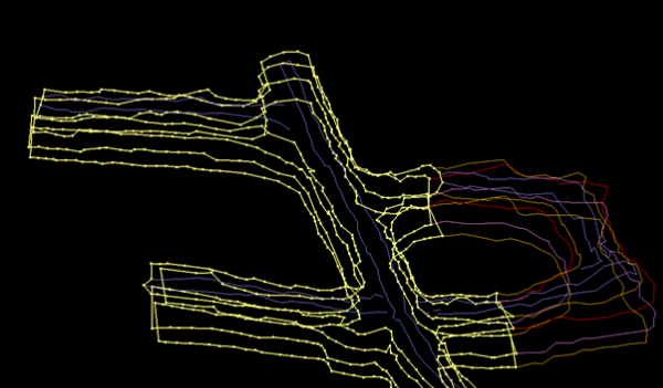
- Split and then join the remaining lines in the pillar object and main drive object at points close to the first splits. Use Design > Object Edit > Join Lines or Properties > Closure > Close to join the corresponding end points of each line. In this example, the Wall line is split close to the points where the Backs lines are split and then the endpoints for the Wall line are joined to each other. The split and join process is then repeated for the Floor line.
- Once the separation process is complete, make the direction of the lines for all objects consistent by selecting all lines in an object, and clicking Design > Object Edit > Consistent. Choose either clockwise or anti-clockwise (counter-clockwise), as long as the numbering sequence of all lines is in the same direction.
- Ensure that the numbering for each line begins at similar points to other lines. Click Design > Point Edit > Resequence and follow the on-screen instructions to align starting point numbers for each line.
- Next, save the pillar object to a layer by again selecting all lines, clicking Design > Layer Edit > Copy and entering a name for the layer in the dialog box. After you click Save, the new layer appears in the Design Databases folder in the Data tab.
- The layer is now ready for the Create Triangulation Survey tool. Repeat the splitting procedure for other pillar objects if required. Otherwise, go to Open to triangulate all objects using the Create Survey Triangulation tool.
- Once the triangulation procedure is complete for each object, use the pair-wise Model > Triangulation Utility > Merge tool to merge all triangulated objects into a single 3D model of the drive.
