Export AutoCAD
Use the this option to export information from design strings, grids, or triangulations to an AutoCAD file. Load design data to the Vulcan workspace that you want to export before using this option.
Prior to using this option, we recommend that you verify that the correct coordinate system and units of measurement are being used.
Splines are exported as a polyline of all the points that Vulcan uses to actually draw the spline (not just the control points). Therefore, if a spline were exported from Vulcan and imported back into Vulcan, it would be imported as an ordinary polyline.
The default file format of the resulting export file is controlled through the File Types section of Vulcan Preferences.
Instructions
On the File menu, click Export, then click AutoCAD (dwg, dxf, dxb) in the File Format column on the left side of the Export panel, and select Design Strings/Grids/Triangulations (dwg, dxf, dxb) for the File Type on the right.
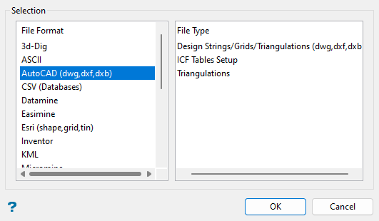
Click OK to open the panel used to export AutoCAD files.
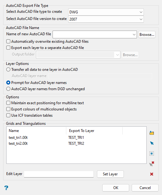
AutoCAD Export File Type
Select AutoCAD file type to create
Select the type of AutoCAD file you want to create from the drop-down list. You can select DWG, DXF, or DXB file types.
Select AutoCAD file version to create
Select the version of AutoCAD file you want to create from the drop-down list. You can select 2018, 2013, 2010, 2007, 2004-2006, 2000-2002, Release 14, Release 13, or Release 11-12.
AutoCAD File Name
Name of new AutoCAD file
Select or enter the name of the AutoCAD file that you want to export the file into using one of the following three methods:
-
Select an existing file in your current working directory from the drop-down list.
-
Click Browse... to select a file from a location other than your current working directory.
-
Enter a new file name to create a new export file.
Automatically overwrite existing AutoCAD files
Select this checkbox to automatically overwrite any existing files with the same name.
Export each layer to a separate AutoCAD file
Select this checkbox to create separate AutoCAD files for each individual layer. If this option is selected, select the folder name in the Output folder drop-down list or click Browse... to select a folder from a location other than your current working directory.
Layer Options
Use this section to define how you want to name the AutoCAD layers.
Transfer all data to one layer in AutoCAD
Select this method to export all the data into a single AutoCAD layer. Enter the name of the layer in the AutoCAD layer name text box.
Prompt for AutoCAD layer names
Select this method to choose new names for each AutoCAD layer.
AutoCAD layer names from DGD unchanged
Select this method to use the same layer names in the AutoCAD file as were assigned in the DGD.
Options
Maintain exact positioning for multiline text
Select this checkbox to maintain the exact location of all lines when exporting a multiline text object. The exported text object will be separated into single line objects that will preserve the positioning based on the line spacing in the corresponding data file.
The lines of the multiline object will be exported as a single object if this checkbox is not selected. In this case, only the first line is ensured to be at the right location whereas the position for subsequent lines of text will be based on the line spacing and font size.
Export colours of multicoloured objects
Select this checkbox to export each line segment and maintain the segment colours. If this checkbox is selected, then the line segment colour will be used to split the chosen object into separate objects. If this checkbox is not selected, the chosen object will be exported as a single object and each line segment would be assigned the same default object colour.
If an object consisting of three line segments is coloured red for segments 1 and 3, and segment 2 is coloured blue, then the DWG export routine will split the object into three separate objects. Object 1 will be created using line segment 1, object 2 will be created using line segment 2, and object 3 will be created using line segment 3. If the original object contained a fourth segment that was also coloured red, then object 3 would be a combination of line segments 3 and 4.
Use ICF translation tables
Enabling this checkbox will translate selected object's colours, layer names, and (for 2D text) fonts according to the project's ICF table translations.
See more information in the ICF Tables Setup section of the File > Import or Export options.
Grids and Triangulations
Use the buttons in this section to populate the Name and Export to Layer columns.
Click ![]() Browse... to choose the grid and/or triangulation file(s) that you want to export.
Browse... to choose the grid and/or triangulation file(s) that you want to export.
In the Open panel, click on the name of the file(s) you want to select from the current working directory list. Use the  icons to go to the last folder visited, go up one level, or change the way details are viewed in the window.
When using wildcard characters, type *> for multi-character and ?> for single character. To highlight multiple list items at once, use the left mouse option in combination with the Shiftkey (this is for items that are adjacent in the list; for non-adjacent items, use the Ctrlkey and the left mouse option).
Move the items to the selection list on the right side of the panel.
- Click the
 button to move the highlighted items to the selection list on the right.
 - Click the
 button to remove the highlighted items from the selection list on the right.
 - Click the
 button to move all items to the selection list on the right.
 - Click the
 button to remove all items from the selection list on the right.
Select the Save Selection checkbox to save the selection list (the right-hand side of the Open panel), in a nominated selection file (.sel).
Click OK in the Open panel to complete grid/triangulation selection.
Alternatively, use ![]() Screen Pick or
Screen Pick or ![]() All Loaded Triangulations/Grids icons to select from triangulations or grids loaded on screen.
All Loaded Triangulations/Grids icons to select from triangulations or grids loaded on screen.
To remove a layer from the list, select the layer name and click ![]() Clear. To remove all layers from the list, click
Clear. To remove all layers from the list, click  Clear All.
The default layer name in the Export to Layer column will be the name of the triangulation or grid. To change the layer name, highlight the layer in the list, enter the new name in the Edit Layer text box, and click Set Layer. This will change the layer name in the list.
Click OK.
The Select By menu will display next for you to pick design data. Choose the selection method and select data to export. Right-click or select Cancel on the Select By menu when you are finished selecting data to export. The layers will be exported to the AutoCAD files as you specified in the Export to AutoCAD panel.
