Design To Actual
Allows a previously mapped face (and any associated sample line drillholes and face photos) to be moved to align with survey pickups and other reference data.
Instructions
On the Face Mapper menu, point to Post Processing, then click Design To Actual.
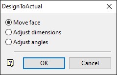
Move face
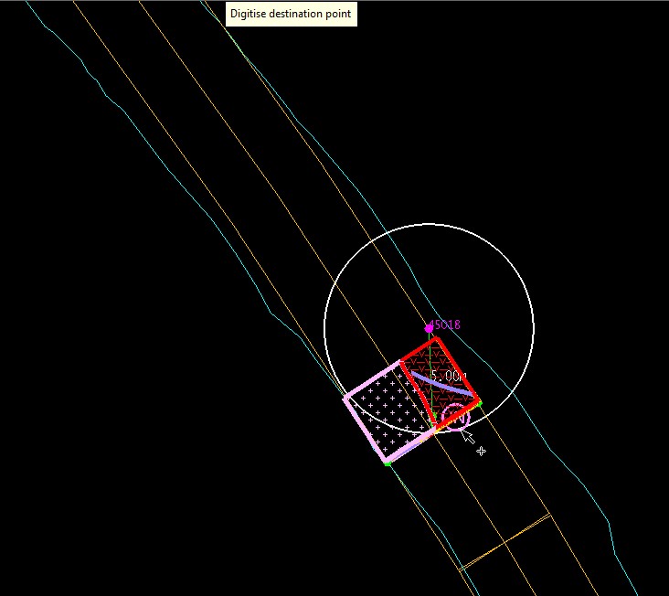
Allows the user to move the face in plan view relative to the recorded distance from the reference survey station. Once ‘Move face’ has been selected the user will be presented with an arc that represents the distance value that was recorded from the reference survey station and a labelled arrow displaying this distance from the station to the centre point of the face. The display settings for the arc and label can be assigned in the 'display' parameters in the Design To Actual settings.
Adjust dimensions
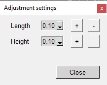
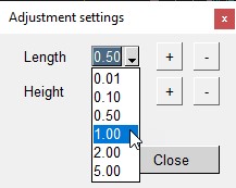
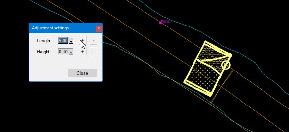
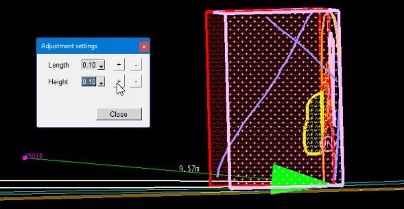
Allows the user to adjust the faces distance from the survey station and also the height, realtive to the original position. Once ‘Adjust dimensions’ has been selected the user will be presented with a floating panel that allows the adjustment of the faces distance from the reference survey station and also it’s height, relative to it’s current position. Each dimension can be adjusted by increments selected from the drop-down list and using the ‘+’ or ‘-‘ buttons to shift the face away from (‘+’) or towards (‘-‘) the survey station and up (‘+’) or down (‘-‘) relative to it’s current position.
Adjust angles
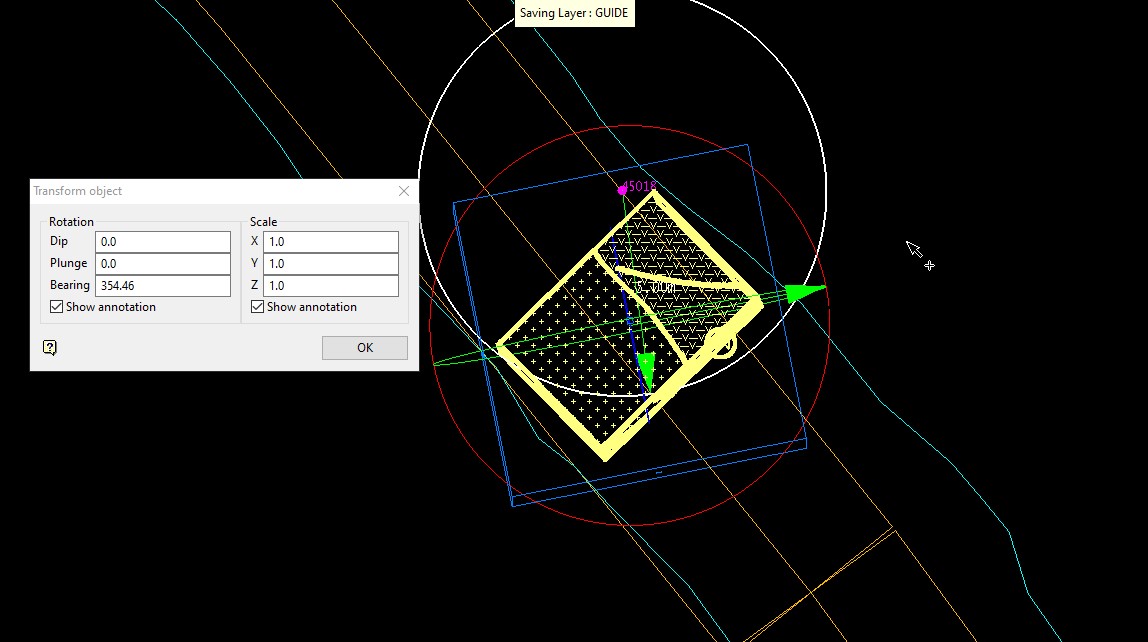
Allows the user to rotate the face in 3D space relative to the centroid of the layer. Once
‘Adjust angles’ has been selected the user will be presented with the Vulcan transform tool (Design > Object Edit > Transform) allowing the 3D rotation of the face, realtive to the center point of all object in the layer.
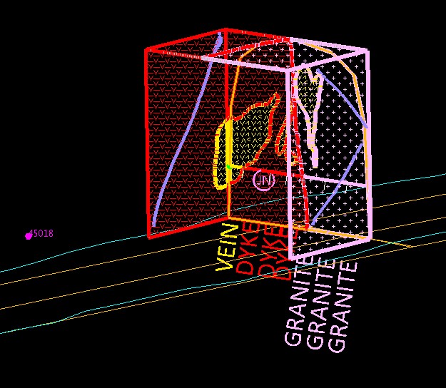
When the face is selected, three circles, centred on the middle of the objects extents, and a cube are displayed. The red circle represents the bearing, blue the plunge and green the dip. The Transform Object panel is also displayed.
Limitations
-
If the face to be moved has associated sample lines recorded, these must be present in the local samples.face.isis database within the current Vulcan project directory in order to allow the sample lines to be adjusted with the mapping polygons. The local isis face drillhole database can be defined in the Samples database > Isis database name in the Face Mapper > Setup > Create Resources panel.
-
The Vulcan screen cannot be rotated while using the ‘Adjust dimensions’ option, and must therfore be rotated as required prior to using this option.
Instructions
Move face
Clicking anywhere on screen will select the nearest point on the arc and adjust the face map to align the bottom centre point of the face to the selected point on the arc.
Adjust dimensions
Once the face has been moved to the desired position the red ‘X’ button will return the user to the ‘DeisgnToActual’ panel.
Adjust angles
To rotate the objects, click and drag on any of the circles (when you hover over one of the circles the cursor changes to the rotate ortho cursor) or enter the rotation angles in the Transform Object panel.
Once happy with the position and rotation of the face select the ‘Cancel’ button on the
‘DesignToActual’ panel. A pop-up prompt will appear asking for confirmation of moving the position of the sample line(s) in the samples.face.isis drillhole database – this is imporant, as this process cannot be undone. If an error has been made ‘no’ can be selected and the adjustments to the face mapping polygons can be undone by using Design > Undo in Vulcan.
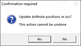
If ‘Yes’ is selected, the sample lines associated with the face will be moved to align with the updated position of the face.