Delete
Delete Triangles from a Solid
Use the Delete option to delete triangles from a solid. This option is used to delete triangles associated with the original polygons (from which the triangulation was generated). You can delete triangles that are inside and/or with vertices touching a polygon or triangles that intersect a plane.
Use the Triangle Delete option if you want to select triangles individually for deletion or you want to delete internal walls, intersecting triangles, boundary triangles or trifications.
Instructions
On the Model menu, point to Triangle Solid, and then click Delete option.
The following panel displays.
Triangles can either be deleted by polygon or by plane.
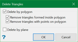
Delete by polygon
Select this check box to delete by polygon. You can delete the triangles inside the polygon (and end plate) and/or triangles that have points on the polygon.
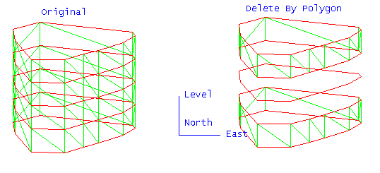
Figure 1: Triangle by Polygon Deletion
Delete by plane
Select this check box to delete by plane. All triangles that intersect this plane are deleted. Once this panel is completed, the Deletion Plane panel displays.
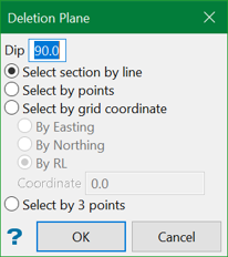
Dip
The dip is the angle of the section from horizontal. Valid dip angles are between -90° and 90°.
Select section by line
Select this option to define the plane by selecting an existing line and specifying the dip.
Only design strings may be picked and it is not possible to pick a line in an underlay. The direction of the view, and therefore the direction of the stepping, depends on the digitised sequence of the line. The digitised sequence of the line can be reversed using the Design > Object Edit > Reverse option.
Select by points
Select this option to define the plane by digitising two points and specifying the dip.
To locate a point precisely, use the Snap to Objects or Snap to Points modes (on the Digitise toolbar). Points may be snapped onto underlays, such as block model slices or triangulations. If you use Indicate mode to select the points, then the points have the current default Z value.
Select by grid coordinate
Select this option to define the plane by using a specific grid coordinate. The grid co-ordinates can contain up to three decimal places. To achieve the best results for the following three methods, we recommend using the Zoom Data Extents button (on the Graphics toolbar) in order to view all of the graphics.
- By Easting - Select this option to enter a specific Easting value (X value).
- By Northing - Select this option to enter a specific Northing value (Y value).
- By RL - Select this option to enter a specific RL value (Z value).
Select by 3 points
Select this option to define the plane by digitising 3 points. To locate a point precisely, use the Snap to Objects or Snap to Points modes (on the Digitise toolbar). Points may be snapped onto underlays, such as block model slices or triangulations.
Using this option will allow you to explicitly define the location and orientation of a plane by indicating 3 points. The first two points define the bearing of the plane, and the third point defines the dip of the plane.
Click OK.
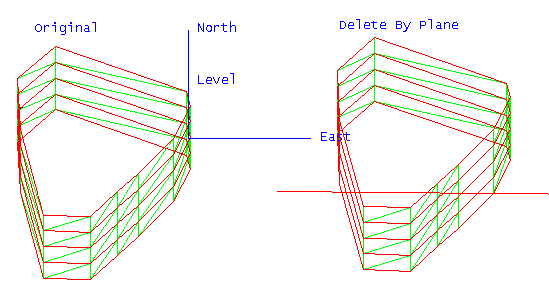
Figure 2: Triangle by Plane Deletion
Define the plane (if applicable), select the polygon (if applicable), and select the triangulation. If there is only one triangulation loaded on the screen, it will prompt to automatically select that triangulation.
The appropriate triangles are then deleted.
Once the triangles are deleted, you will be prompted to save the edited solid, restore back to the saved solid, or perform another deletion.
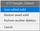
Save edited solid will open up Save Triangulation panel and allow you to save the resultant solid.
Restore saved solid will revert back to the original solid without performing deletion.
Perform another deletion will take you back to the start of the deletion process.
