GEODAT
The following panel displays.

![]() Note
Note
The GEODAT download file must have been downloaded with the GEODAT instrument being in DMS mode.
Reduction Selection panel
Unless your download file only contains GEODAT coordinates,always select the Download file contains non-coordinate data option.
Station library
Main library name
Enter, or select from the drop-down list, the name of the library in which the system will first search for the station's coordinates.
Alternate library name
Enter, or select from the drop-down list, the name of an alternate library in which the system will search. Specifying an alternate station library is optional.
Reduction file
Enter, or select from the drop-down list, the name of the download file that you want to reduce. The drop-down list contains all of the download files that are applicable to the GEODAT instrument, that is, files with the extensions .geodat_in, .job and .raw.
Select Next.
The following panel is then displayed.
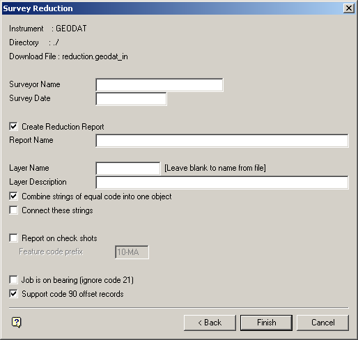
Survey Reduction panel
Surveyor Name
This is an optional alphanumeric field of 20 characters for the surveyor name. The default is set to your user name.
Survey Date
The survey date is optional and, if entered, must follow the format dd-mon-yyyy. For example, 18-Mar-1998. The default is the current system date.
Create Reduction Report
Select this check box to save the reduction report to a specific file. You will need to specify the report file name. The default is the name of the download file (excluding the file extension). The maximum size of the file name is 40 alphanumeric characters. The extension .srvrpt is automatically added to the name when the report is generated.
Layer Name
Enter the name of the layer for the data points. If left blank, then the project name record or filename record from the reduction file is used to name the layer(s).
Layer Description
Enter an optional 40 alphanumeric character description of the layer.
Combine strings of equal code into one object
GEODAT points are feature-coded using a special feature code record. Select this check box to place all the points in the same job with the same feature code into one object. If unchecked, then the Vulcan objects are formed based on strings of consecutive points with the same feature code.
For example, if the check box was checked and the download job contains one job with 10 sequential crest points, then 3 toe points, then 5 crest points again (with the same code as the first 10 points), you would get 2 objects, that is, a crest with 15 points and a toe with 3 points. If the check box was not checked, then you would get 3 objects, that is, a crest, a toe and a crest.
Connect these strings
By default, if the survey code defines this object as a string object and not spot data, then only consecutive points in the download job are shown connected by a line on the screen. If the check box is checked, and the object is a string object, then all points of that survey code will be shown connected. Using the example above, point 14 in the download file would be connected to point 10 if the check box was checked. If this check box is not checked, then these two points will not be connected thus causing a line break in the crest object.
Report on check shots
Select this check box to report on the check shots. Check shots are shots taken to known stations to check the setup station coordinates and orientation. A check shot is identified by a special survey 'feature' code (prefix). If the shot's survey code begins with the prefix, then the remainder of the survey code indicates the station name, For example, CHSTAT1 indicates a check shot to known station STAT1. The default prefix is CH (for Check), although this can be changed on the panel.
The report will have an extra line showing the easting, northing and level misclose (error compared with check shot station coordinates from station library), along with a linear misclose ratio (planimetric misclose divided by length of the line), For example,
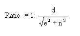
where e = easting misclose; n = northing misclose; d = reduced horizontal distance to the check station from instrument station.
Job is on bearing (ignore code 21)
Select this check box to ignore any code 21 records (backsight shot). Some downloaded jobs don't include a backsight shot because the horizontal angles in the job are bearings. Therefore, no bearing swing is required to be calculated.
Support code 90 offset records
Select this check box to use a code 90 record for horizontal offsetting if no other horizontal offsetting codes are being used for a particular shot. If this check box is checked, then a code 90 record of the correct format will be used to calculate the offset that is to be applied to the shot. Refer to Appendix C : Data Recorder Interfaces : GEODAT for a detailed description of the code 90 record.
![]() Note
Note
This check box will be checked by default; however, we recommend that you clear it if you are using the code 90 record for a procedure that is not supported by Vulcan.
Select Finish.
The GEODAT Reduction Data Summary panel is then displayed. This is a summary panel that to verify the details prior to forming the reduced objects.
Select OK to accept the panel. The following panel is then displayed.
The calculated results are then displayed in the Report Window and, if requested, saved in the nominated file.
See Appendix A for an example of a Reduction (SDR22) report.
